
| ▲ Electronics |
Note (01/03/12): I was sent a link to another site which has an excellent teardown and analysis of an induction cooker. It's far better than this page, so I'd strongly suggest having a look at it. Link: http://openschemes.com/2010/11/11/1800w-induction-cooktop-teardown/
Note (14/11/10): This was written before I knew very much about induction heating, and probably shows in the writing. I intend to put up some better pages on induction heating at some point. If I have made erroneous statements here, I probably know about them know and apologise!
Induction heating (IH) is a process for heating metallic articles using electric currents induced in the article. Typically, a coil with a few turns of heavy copper wire or tube is wrapped around the article to be heated and an RF current is passed through the coil. The frequencies used can be anywhere from 50kHz up to the MHz region, depending on the size of the object to be heated, and the desired depth of heating.
For further information on induction heating and commercially available power supplies, please check out the following sites:
http://www.richieburnett.co.uk/indheat.html
http://webpages.charter.net/dawill/tmoranwms/Electronics.html
IH can be used to heat parts with no physical contact between the exciting coil and the part. It can therefore be used in vacuum. Since there is no flame used, IH is an extremely clean and efficient process.
My interest is mainly its use for vacuum brazing. For example, you can do incredibly neat stuff like brazing metal to ceramic in a vacuum.
I phoned up the UK distributer for Ameritherm and eventually managed to get quotes for the HotShot 1kW and 2kW models. The prices were £6,000 and £7,000 respectively. At which point I thought, surely it can't be impossible to make one for a lot less? (I tend to think that about a lot of things!). So begins the saga of induction heating.....
The basic elements of the power supply are:
Although I thought this shouldn't be too hard to do from scratch, I decided to start off by looking at a commercial induction heating supply, in the disguise of an induction cooker.
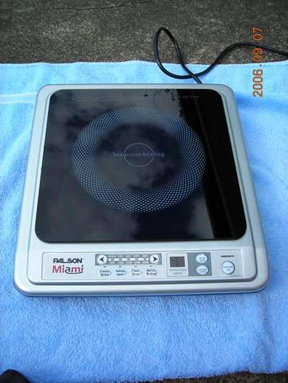
Single-hob induction cookers are very easy to come by on EBay, and I managed to pick up a brand new 2kW Palson Miami hob up for £54.
Top of the cooker, showing hob and control panel.
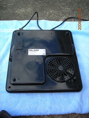
Underside of cooker, showing cooling fan.
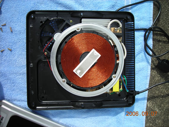
This is the view which greets you after removing the lid. The cooling fan is at the top left. The heating coil (although I call it a heating coil, remember it's NOT a resistive heating coil!) is the big thing in the middle. The white rectangle contains two temperature sensors. There is an earthed guard ring around the coil (to prevent stray fields?) and the driver PCB underneath.
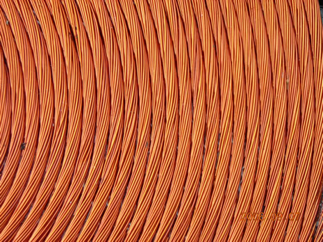
Top view of the induction coil.
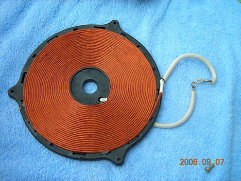
Thought this took a rather nice picture!
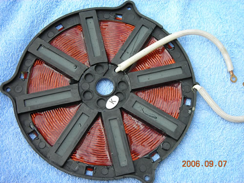
Rear view of the induction coil. Notice the eight pieces of ferrite bar arranged radially around the coil. This will concentrate the field from the coil to immediately above the hob's surface, so it will only heat stuff which is actually sitting on the hob.
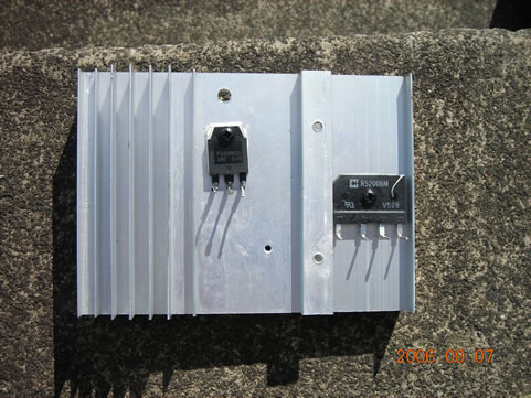
And this is the thing that makes it tick. I had to desolder these from the board to see their model numbers. The 3-pin thing on the left is the IGBT (insulated-gate bipolar transistor) which drives the induction coil. It is a Fairchild FGA25N120AND. You can download the datasheet here. The 4-pin thing on the right is a bridge rectifier. This rectifies the mains directly and provides the DC drive for the induction coil.
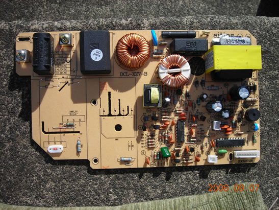
A shot of the driver circuit board.
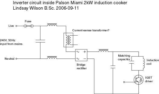
I've only mapped out the inverter side of the circuit, as it's got nice big tracks which are easy to follow! The actual control circuit looks a nightmare, but hopefully I won't have to worry about it much.
Let's follow things from left to right. First, on the mains side, we have the fuse. Next come a cap & two inductors, presumably to filter the mains coming in. The two inductors are wound on the same toroidal core. These inductors are wound on the right-hand core in the picture of the PCB above.
Next we have a little thing I've called a current sense transformer, although I have no idea what it is. I'm guessing it's something of the sort, since the primary is just a single turn of wire. I don't know what this would be for. I did think on disconnecting it to see what happened but if it's to protect something else, I'd maybe better not!
We then have a bridge rectifier to provide DC to the inverter circuit proper.
Next we have an inductor in series with the +ve line, and a cap connected between it and ground. I don't know what the purpose of these is, but Richie Burnett's page I think explains something of the sort, I'll have to read it more closely.
Then we've got the business end of things. The matching capacitor and induction coil provide a resonant tank circuit which is driven by the IGBT.
The cooker has various operating modes with different power settings. I wanted to see how the cooker controlled the power of the induction coil, and what the signal to the gate of the IGBT looked like.
So, I merrily soldered two wires to the IGBT in the cooker, one to the gate, the other to the emitter. I then reassembled the cooker, turned it on and went to connect the emitter lead to the negative input of my oscilloscope. FAZOOOM! Big crackly spark......Oh Dear. Luckily neither the scope or the cooker was damaged.
I couldn't understand why it happened, but a call to the good guys in the electronics lab at uni soon revealed why. The bridge rectifier runs directly off the mains. This means that the "negative" output of the bridge rectifier will actually be shooting around w.r.t. ground because it is referenced to ground through the mains. When I tried to connect that to the negative lead of my scope (which was grounded), the inevitable happened......
One thing the guys suggested was to use a high-voltage differential amplifier to measure the difference between the emitter and gate voltages. I planned on trying this, but I decided to start off with some bits I had closer to hand.
Basically, I used two voltage-dividers to divide the voltages of both the emitter and gate signals with respect to earth, then two op-amps to buffer these signals, and finally a differential amplifier to measure the difference between these. I used 741's as the op-amps, but any old op-amp would do. I just happened to have 40 of the 741's lying about!
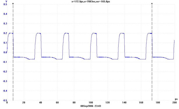
These are three waveforms of the gate drive voltage when the induction hob is running on the "boiling" cycle. The load is 1L of water in a mild steel pan.
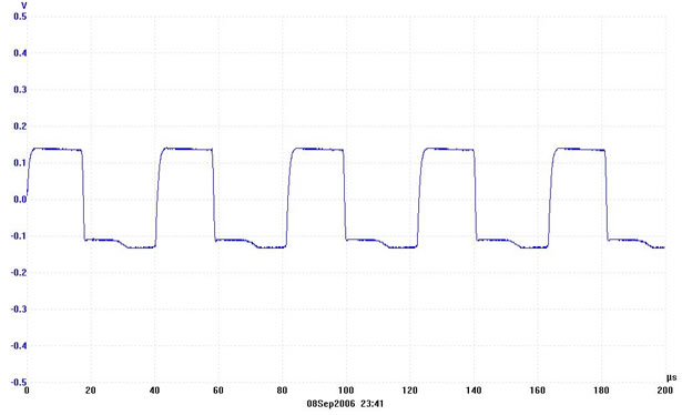
When running on the boiling cycle, the cooker control circuit is delivering maximum power (2kW) to the induction coil.
From the above waveforms, we can see that the running frequency is 24kHz. The drive amplitude works out at 15V (remember there's a potential divider on each input of the circuit). The duty cycle of the square wave (%-on) is 46%.
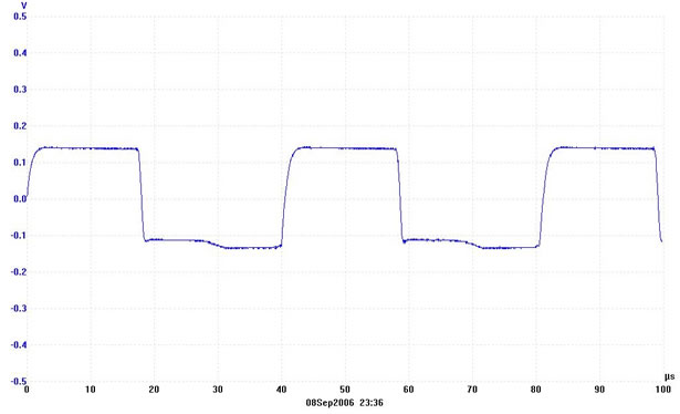
One thing I noticed when I was watching the waveform as I started up the cooker is that both the duty cycle and running frequency change from startup before they reach their steady-state values. The next waveform is taken immediately after starting the cooker (again on the boiling cycle).
The frequency is 30kHz, amplitude 15V and duty cycle 22% on. I would've expected the duty-cycle change (the cooker controls the power by PWM of the signal to the gate of the IGBT, so this could be explained by a kind of "soft start" circuit for the induction coil), but I can't figure out the change in frequency. I suppose one explanation might be that the circuit is self-tuning and it takes a while for it to settle on the correct operating frequency. But it takes several seconds, which seems rather long.
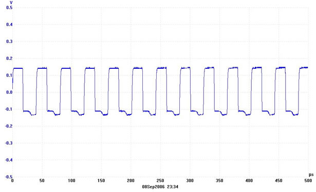
The saute cycle allows you to adjust the power level of the cooker to one of 100, 300, 1200, 1600 or 2000W. I only looked at the waveforms for the 1200W and the 1600W setting.
This is the waveform for 1200W:
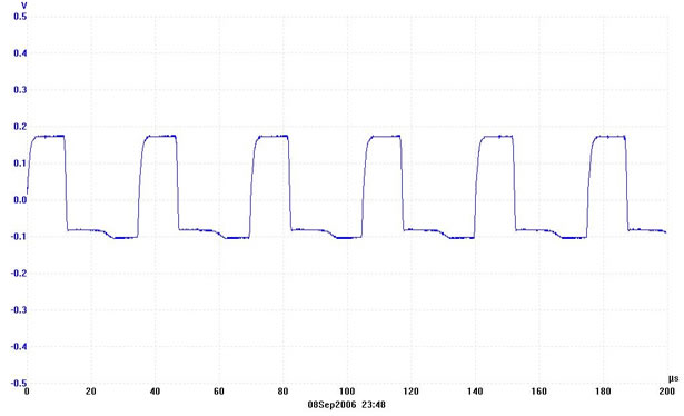
Frequency 28kHz, amplitude 15V, duty cycle 36%.
This is for the 1600W setting:
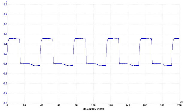
Frequency 26kHz, amplitude 15V, duty cycle 41%.
Although I didn't record a waveform for the 2000W setting, the results for it were frequency 24kHz, amplitude 15V, duty cycle 45%.
To summarize:
| Power level (W) | Frequency (kHz) | Amplitude (V) | Duty cycle (%) |
| 1200 | 28 | 15 | 36 |
| 1600 | 26 | 15 | 41 |
| 2000 | 24 | 15 | 45 |
The position of the pan on the cooker also has small effects on both the frequency and duty cycle of the driving waveform.
The main question is why the frequency of the IGBT inverter changes depending on the power setting, the time since turning the cooker on and the position of the pan on the hob. It may be an unintentional result of changing the duty cycle, but I don't see how that is the case.
It also isn't clear how the frequency of the IGBT inverter could be automatically tuned to the resonant frequency of the tank capacitor and work coil to avoid damage to the IGBT.
| ▲ Electronics |