| ▲ Electronics |
I made this jig a couple of years ago but never quite got around to describing it. I designed it when I needed to do some double-sided circuit boards, and was having difficulty in accurately aligning the transparencies for both sides of the board. "Traditional" techniques, such as taping the transparencies together into a little wallet and sliding the board between them, proved tricky, especially when it came to flipping the board over to expose the other side. After a bit of thought, I came up with this.
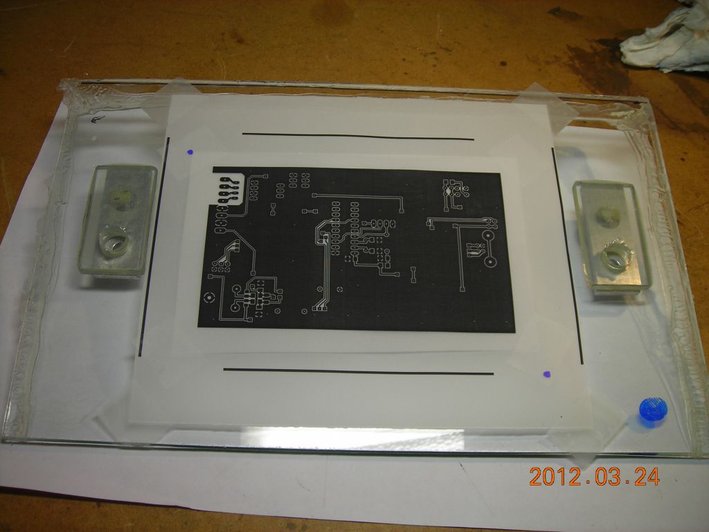
It consists of two sheets of 4mm plate window glass, approximately 10" x 8". The first photo below shows both of them laid out. When I took these photos, I was doing some electrolytic etching rather than PCBs, so there are two laser-cut vinyl masks on the glass plates instead of transparencies. The principles are the same, though.
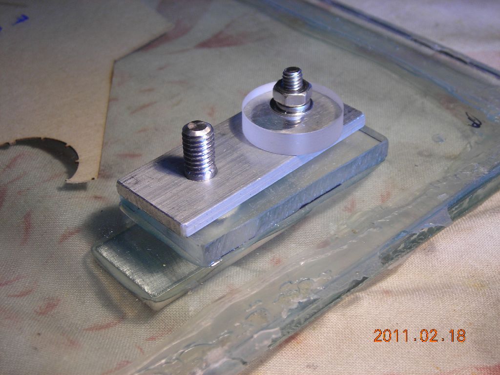
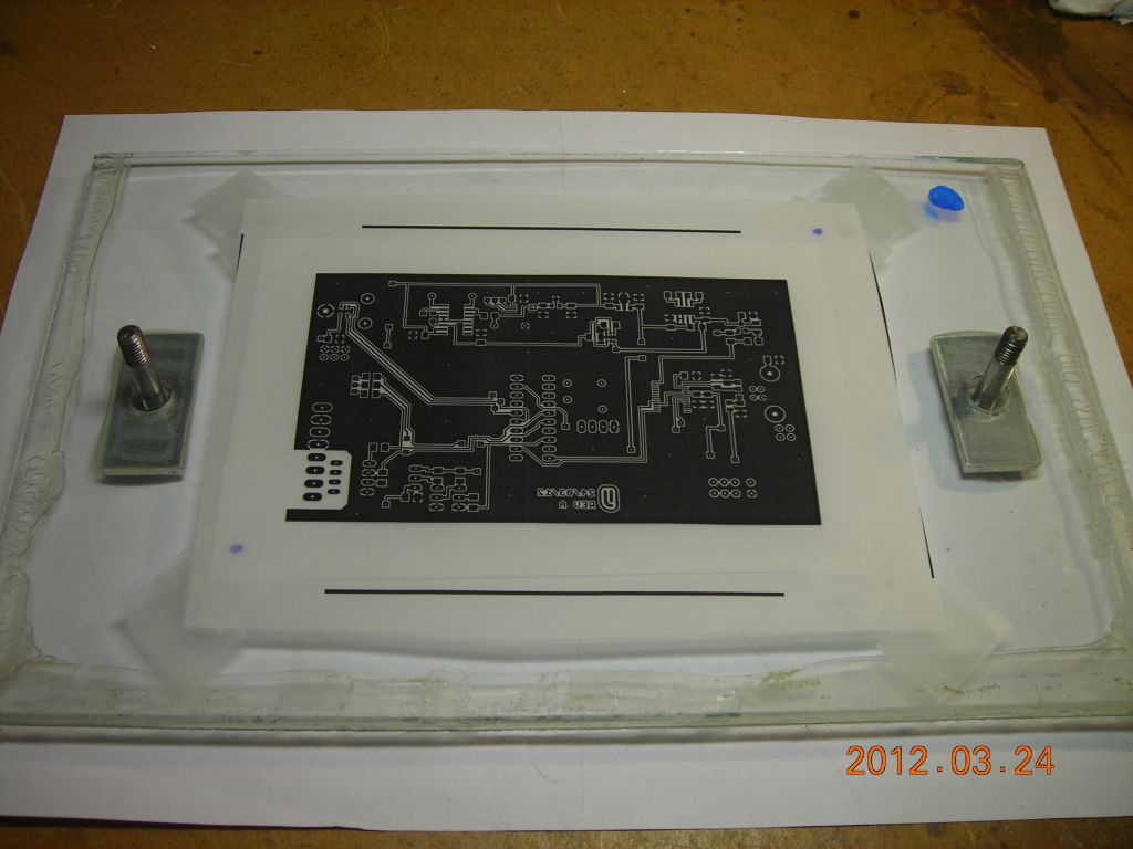
One glass plate (upper in the first photo) has two 6mm-diameter steel pins attached to it as shown at the bottom of the second photo. These are attached by screwing to an aluminium plate on the underside which is glued to the glass. The tops of these steel pins are threaded.
The steel pins pass through over-sized holes (½") in the top plate; therefore, when the top plate is placed over the bottom plate, there is a few mm of lateral movement available. The steel pins next pass through aluminium plates with exact 6mm holes - once the glass plates are aligned as desired, these aluminium plates are clamped to prevent movement. Thus, the two glass plates can be separated and placed back together, with the pins ensuring accurate, but adjustable, alignment between the two.
If that description was a little obtuse, hopefully the pictures are self-explanatory!
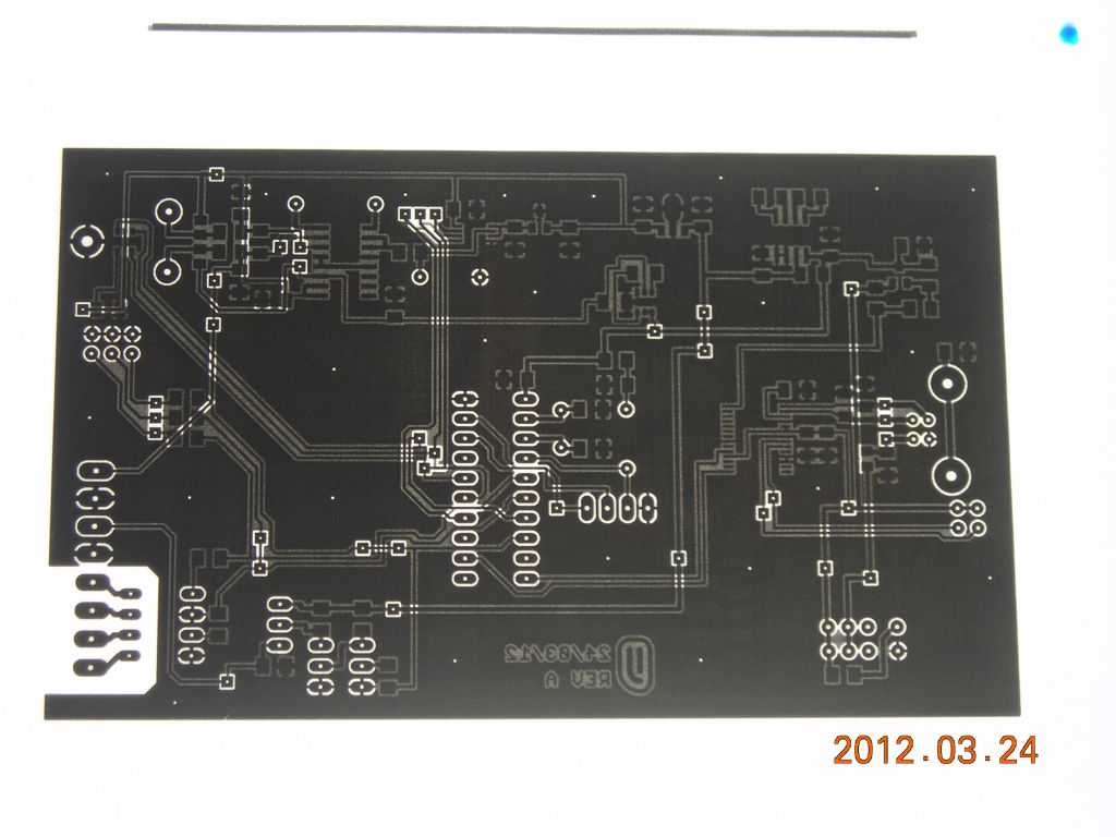
In operation, the transparencies, masks, or whatever are stuck to each glass plate. The glass plates are then placed together and aligned without a substrate present, by looking through them at a light source. It's easy to tell when they are aligned - see the fourth photo below. The pin holes are then clamped, the plates separated, the substrate inserted, plates back together again, and it's now ready for exposure. I have done double-sided surface-mount boards with this and the alignment is pretty exact - more of a worry is the non-linearity of my laser printer.
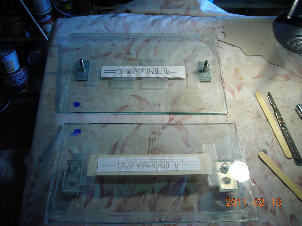 Plates separated, showing vinyl masks attached |
 Closeup showing lower locating pins and upper sliding plate with hole |
 Plates together |
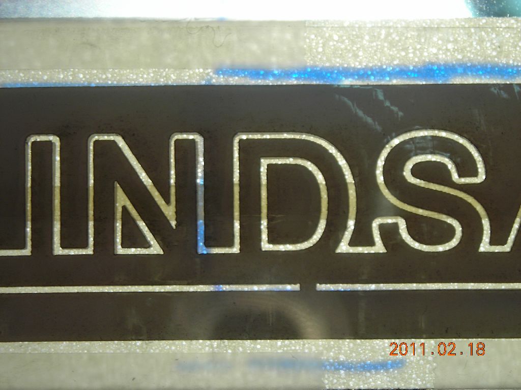 Good mask alignment |
Note: the silicone mastic which is visible around the edges of the glass plates has nothing to do with the jig - the glass was originally a shed window which was sealed into the frame.
Here is a better example, showing an actual PCB being exposed.
 Bottom transparency |
 Top transparency |
 Both transparencies overlaid and aligned. Note good alignment of through holes and vias. |
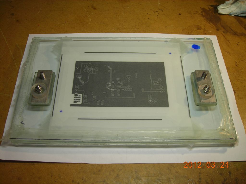 Plates together |
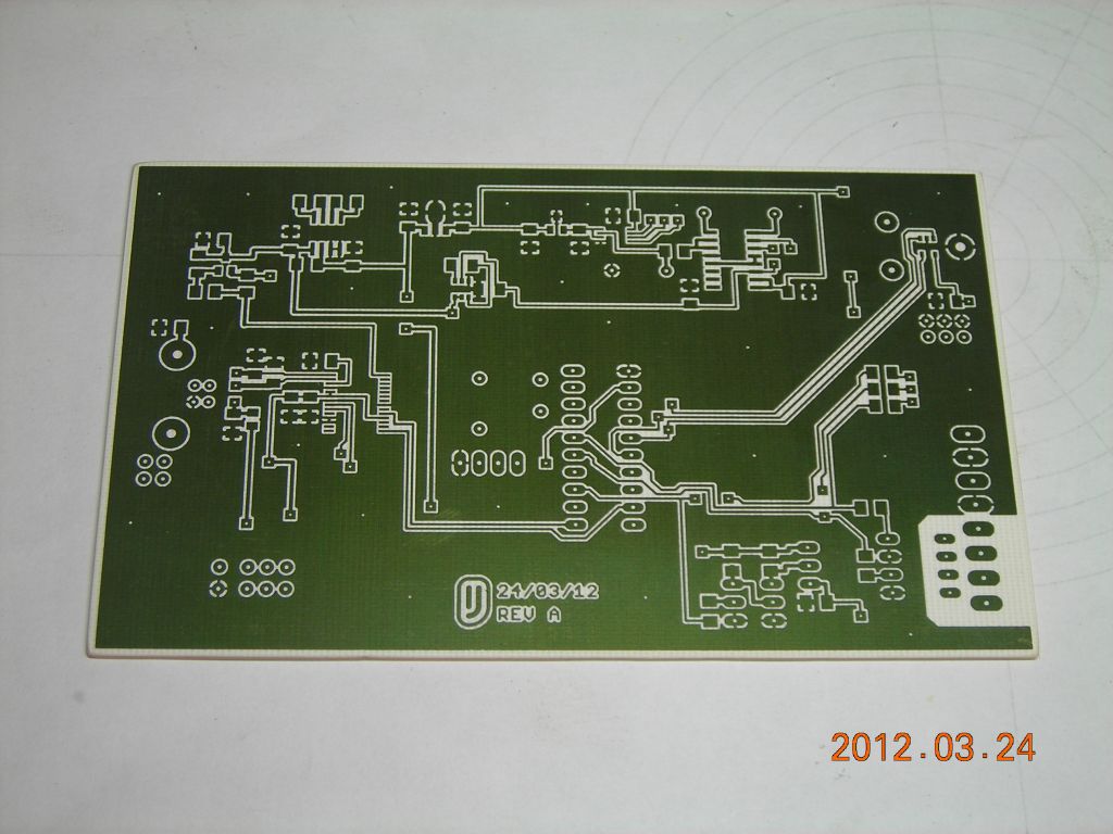 Finished board - top (photoresist still present for clarity) |
 Bottom |
| ▲ Electronics |