Yet more additional information (19/10/11):

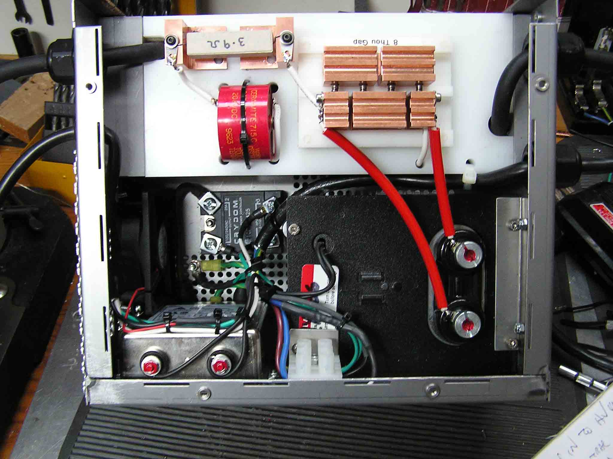
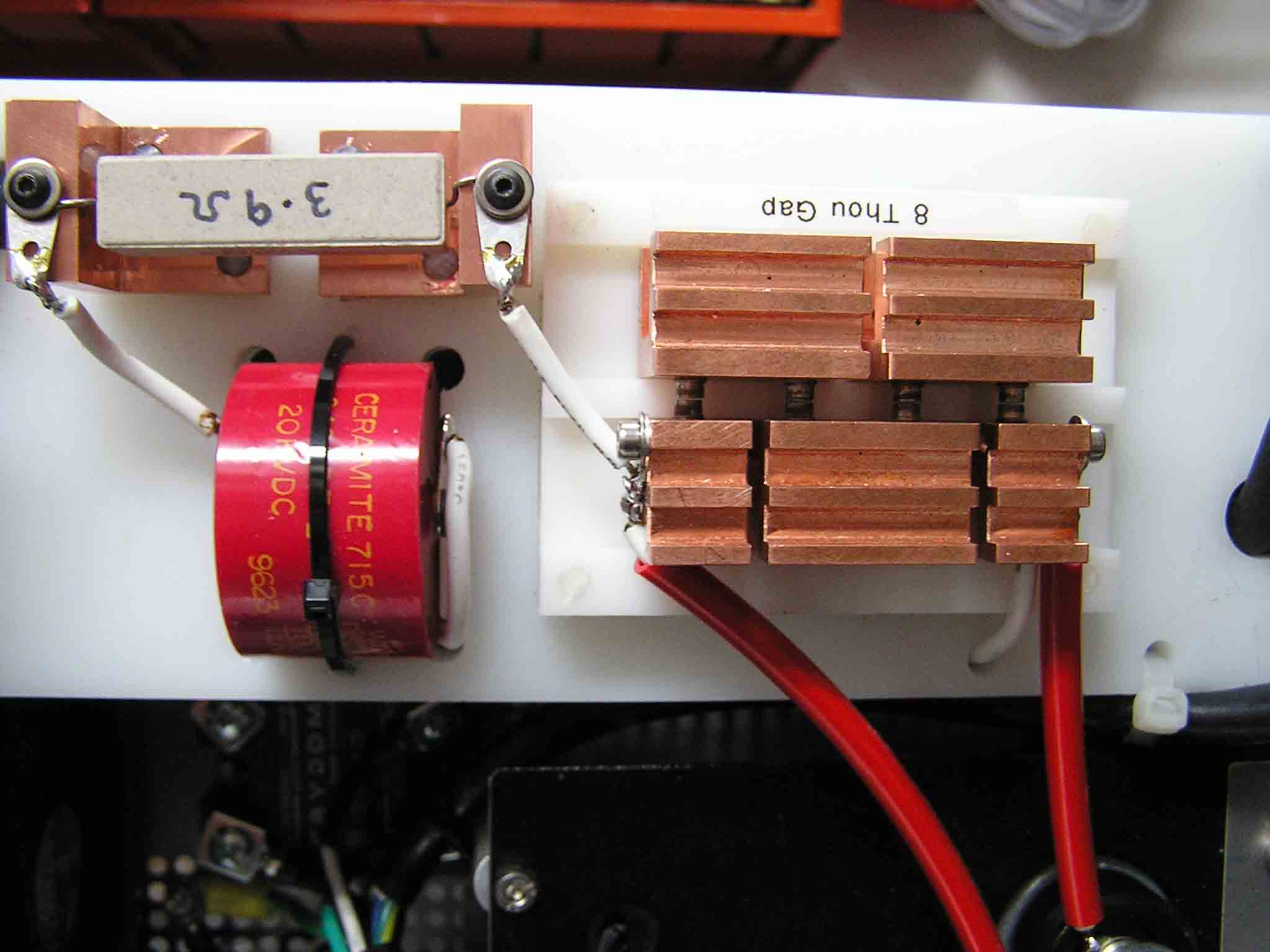
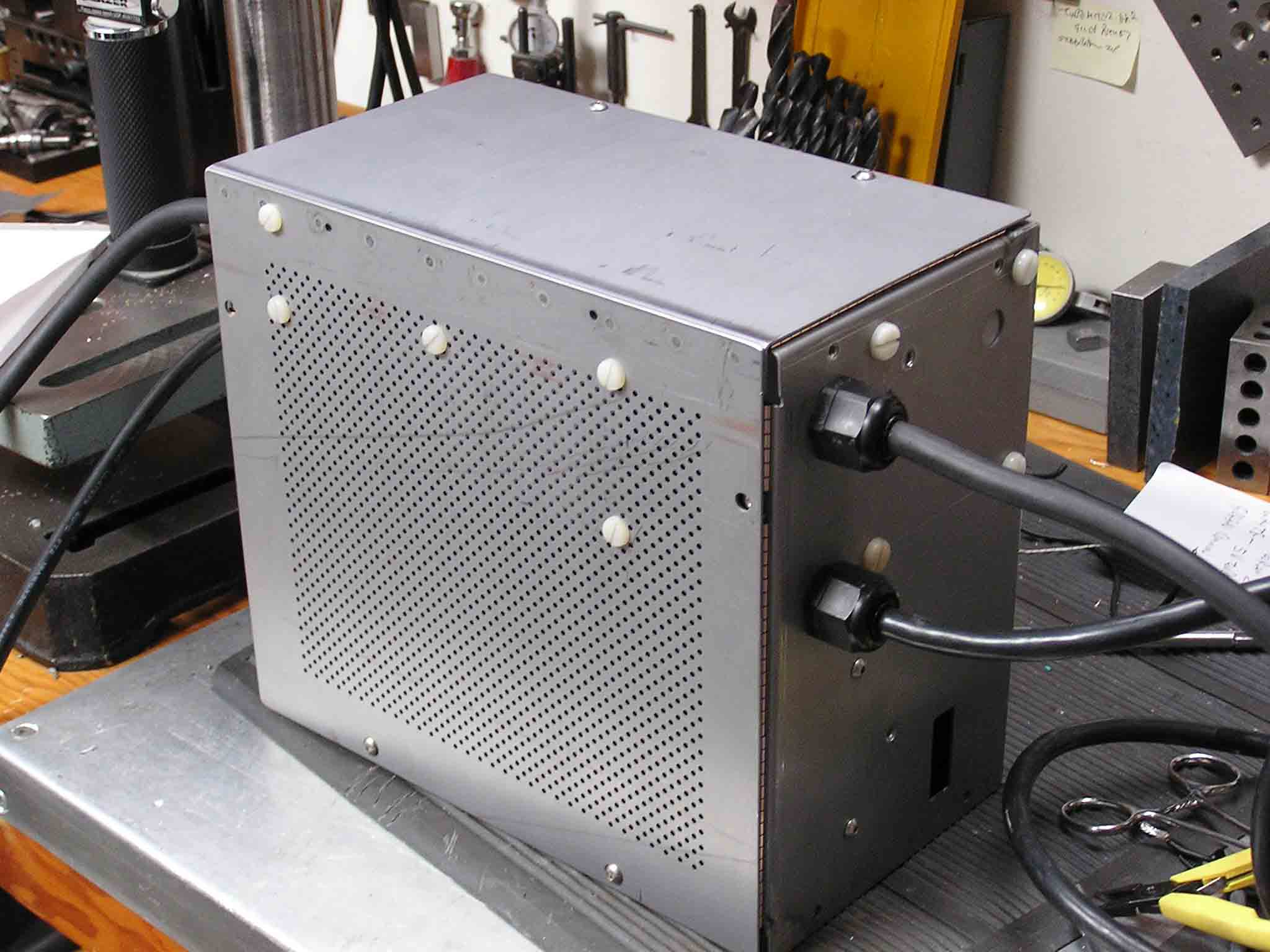
I happened to check the original page link (http://www3.telus.net/public/a5a26316/TIG_Welder.html) and it seems to be working again, and updated more recently. I'd therefore suggest going to the current page instead of looking at my copy here.

Please read - additional information by Lindsay Wilson (lindsay@imajeenyus.com) on 25/04/11.

This page was originally from a website at the address http://www3.telus.net/public/a5a26316/TIG_Welder.html. I found a link to it in a forum post on building TIG welders. However, as of 25/04/11, this URL is no longer valid. Fortunately, with the magic of the Internet Archive Wayback Machine (web.archive.org), I was able to piece together the page and the associated files. They are reproduced here exactly as they appeared on the original website. The only change I have made is to make the images link to bigger versions. The date of the Wayback backup is 9th March 2009.

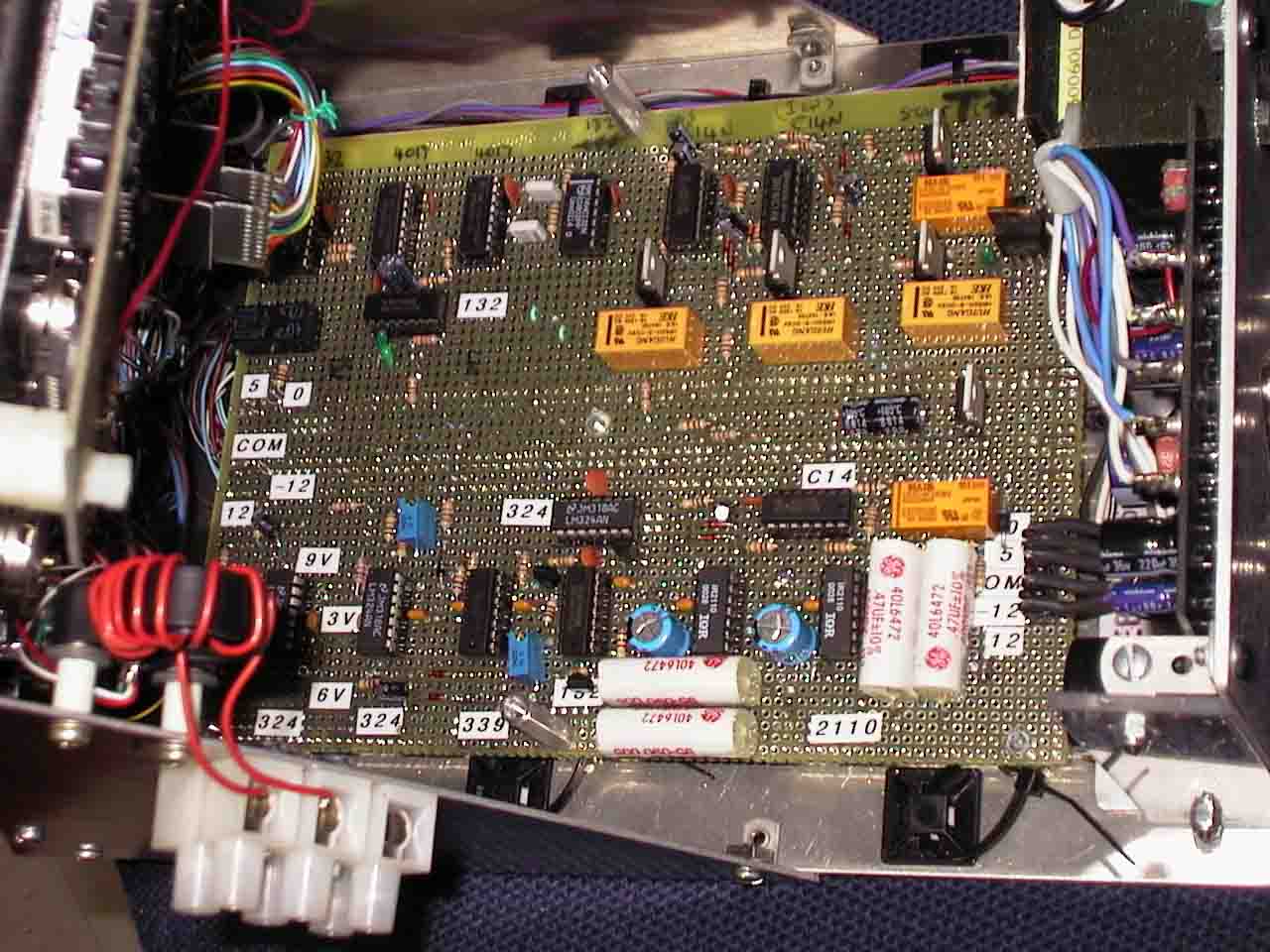
I make no claims as to the veracity of the material here, it is provided solely for information. All content is by the original author, Dave Barrett, whose email is dave.barrett@creo.com; however, I don't know if this email address still works.

TIG Welder 180 Amp (Home Built)

This project is a collaberative effort between myself and my old friend Will Coetzee and is built around TTL and CMOS logic to keep it simple, repeatable and easy to trouble shoot.

We purposely did not use a micro to control it because most folks don't have the capacity or experience to work with or program those devices.
We chose to use through hole components also because the average person doen't have suitable facilities at home to build with SMT parts as antistatic work surface, stereo microscope and proper soldering station would be required at minimum.
All the information I have currently available is on this page ! At the present time we are both very busy with family and work and will get back to the project to complete the detailed information as soon as possible.

Please DO NOT email asking for parts lists, Gerber files, ...I have none done up yet and as for PC boards, we are not selling kits or parts.

The welder as presented requires you to supply a simple basic AC Arc (stick) welder, this provides the AC voltage at whatever suitable current range you elect to purchase and our controller as described will give full control of the weld current be it AC or DC. More details and specs added at the end of the article.


Test PCB on Vector board


Top close-up of Front panel
Front Panel lower portion close-up

Frequency counter

Finished Foot Peddle control with geared potentiometer and Opto switch.

Basic Arc Start components in case

Bridge Diode IGBT Cooling Tower

Partially Wired Arc Start Unit

Home made Spark Gap unit, Current Limiting resistor and Resonating Capacitor
Completed and buttoned up Arc Start unit
Folding Ferrite (6 pcs used as core material to improve coupling

This page details the design, construction and fun involved with building my version of a modern TIG welder with 180 Amp capacity and all the features of present day state of the art TIG machines at a fraction of the cost.

The project started out as an excercise in frustration. As I'm sure you are aware if you are reading this there is little real in depth information available on the web detailing the design of welders.
Lots of block diagram and generalisation......but no real substance, probably because the welding companies don't want anyone to see how simple it really is to produce a TIG unit with real world capability.

After over a year of searching out what was required I finally ended up going to component manufacturers application sheets and found more there than was generally available from welder companies.

Many modern welder front panel's were looked at and many dozens of spec sheets studied to gain a list of requirements, then it was simply a case of reproducing those function's simply and cheaply.
The descision was made early on to build using descrete I/C's for three main reasons. Firstly they are easy and cheap to obtain for anyone wanting to copy the design.
Secondly Microprocessors are great and simplify things a geat deal but one has to have programming knowledge and the equipment neccesary to actually get the firmware into the chip....not everyone has either.
And thirdly if fault finding is required descrete TTL and CMOS is far easier to troubleshoot with average home type test equipment (VOM, Freguency Counter, Oscilloscope etc)

My list of functions was growing longer by the day so I started to construct a basic (Alpha) test bed, a small alloy chassis with three controls and a littlel piece of Vector board, it soon became clear this was too restrictive to accomplish all the functionality I had envisioned so a larger (Beta) version was embarked upon, it has a hinged front panel to allow easy access for adding parts as I went along.
I have put a picture so you can see the crude but functional test bed Beta unit......yes I know its crude but remember its only a test bed !


Added four new pictures and nine PDF links for the finished Arc Starter Unit.
I have recently replaced the Arc Start circuit after considerable experimentation I deduced that the Flyback Transformer was simply too loosely coupled to deliver the required power to the heavy current coupling transformer (Yes, some of you told me that ;-) but I had to try myself and see ;-) Anyway a neon sign transformer was procured, as was a commercial spark gap and door knob cap, I tried building a cap (2500pf at 30Kv) and it had huge losses in the dielectric and the home built spark gap (made with machine tool tungsten carbide tips) also was not the best so I went with used locally available commercial units (the price was right ;-) With the new circuit which is taken from a welder handbook, the spark gap / cap primary winding increases the dangerous and unsafe frequency from 60Hz (coming out of the Neon trans) to around 1Mhz at the primary of the coupling transformer. I had a few iterations of the coupling unit too, found it didn't have enough coupling in its initial forms, so I added some ferrite cores taken from those folding split ferrite units, chucked 6 into the centre of the core of the coil, (4 would do !). I'm using 6 turns of 15Kv wire for the primary winding and 18 turns of welding cable for the secondary, closely wound on top of the sec winding. This circuit works really well with lots of power at a good (safe / skin effect) frequency, I have touched it to make sure ;-) The arc is about 6mm long and very strong. The final circuit uses a 2200pf doorknob capacitor with a rating of 15Kv, I rebuilt the commercial spark gap assembly as it was only intended to start arc lamps, I increased the heat sinking capabilities of the device considerably, also added a 3.9 ohm wire wound resistor to limit the current in the circuit. The choice of this resistor is somewhat critical !! I found that the white or grey square bodied ceramic types are best as they apparently add little inductance to the circuit, while the older green or black round bodied units upset the ballance of the circuit by adding way too much inductance caused by the wire wound nature of their construction. !
- Complete System Drawing
- Control Panel Drawing
- Arc Starter / Stabilizer Drawing
- Frequency Counter Drawing
- Timing Circuitry Drawing
- Controller Drawing
- System Power Supplies Drawing
- 100 Amp Power Stage Drawing
- 200 Amp Power Stage Drawing
Here are a couple of the PCB Layouts finished so far in PDF format.
- PCB Bottom view
- Top view mirrored
- Control board bottom
- Control board mirrored

Some of you have asked which IGBT's I used ? Well, the reason the numbers were left off the diagrams was that it was deemed best to leave the device selection up to the builder and availability in his or her particular area.
Just for interest the devices used in the Alpa test version of the unit were IRG4PC40F (600v 27amp, these will handle 49 amps in pulsed mode ! 4 pieces were parralleled for each section of the H bridge.
I later switched to a higher current device G30N60B3D which is good for 600v 60amp (220amp pulsed). Also used was an ultra fast switching diode to protect the device junctions part number: MUR1540 (600v 15a)
The other question that comes up in emails quite often is the Current Sensor, A three wire Honeywell device with a split core that slips over the welding cable was used, part number: CSLA1GF.
Finally the foot peddle opto sensor is a GP1A05, This I feel is more reliable than mechanical microswitches.
********************************************************************************************************** Note on specifications for the welder that many folks are asking about, hope this list help answer your questions.

1/ AC-DC welding variable via two thumbwheel switches from 1% (all Negative) right through full range of AC to 99% (all Positive) These are connected via J4 Con24.
AC frequencies available from 15 to 400 Hz
2/ Pulse Frequencies fully variable from .3 to 10 Hz This does away with having to pulse the foot peddle on thin materials.
3/ Variable control for Maximum Welding Current available to the Foot peddle control.
4/ Variable Start Current (period of higher current available (higher than starting foot peddle position, IE. max setting on front panel control) for short time heating of thick materials)
5/ Variable Start time for above.
6/ Variable End Current (Crater).
7/ Variable End Current time.
8/ Variable Gas Start time.
9/ Variable Gas End time (Dwell).
10/ HF Arc Start.
11/ Opto Interupter / Potentiometer foot peddle current control.
The arc Start can be easily switched off when not needed and an auto off position will be added when time permits.
12/ The basic unit documented here still needs a Buzz Box AC Arc Welder to supply the welding current.
13/ One question that has come up a couple of times it relative to timing in the "H" bridge, the leads of the H bridge sections must be kept as close to identical to each other as possible so the timing remains the same for each half....IE/ if the halves get swithed on together due to messed up timing caused by excessive capacitance of long leads then there will be a problem possibly damaging one or both set of IGBT's, this is a normal situation with all H bridge circuits and does need to watched for.
Hope this helps clarify things a bit guy's.
Thanks for all your interest, sorry if I'm a bit slow sometimes replying but the shear quantity of email enquiries is sometimes overwhelming............Dave
***************************************************************************************************************

For anyone needing more information please:Contact Me
Page Last Modified: 8 September 2006