| ▲ Electronics |
18/03/14: Interesting page which compares the performance of a couple of other BLDC drivers - http://www.kerrywong.com/2014/03/02/testing-of-two-three-phase-bldc-motor-drivers/ (via Dangerous Prototypes).
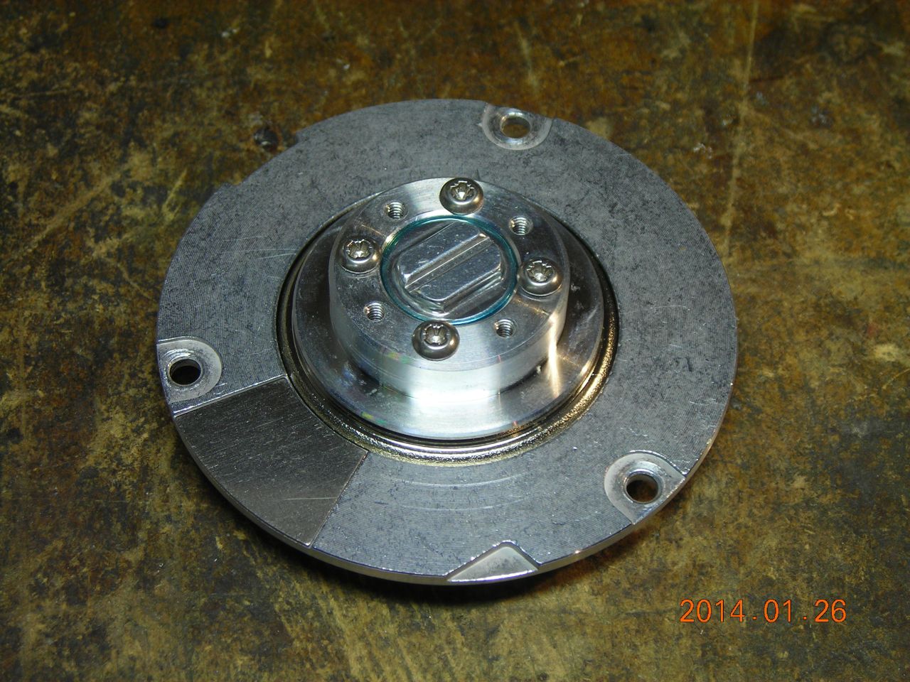
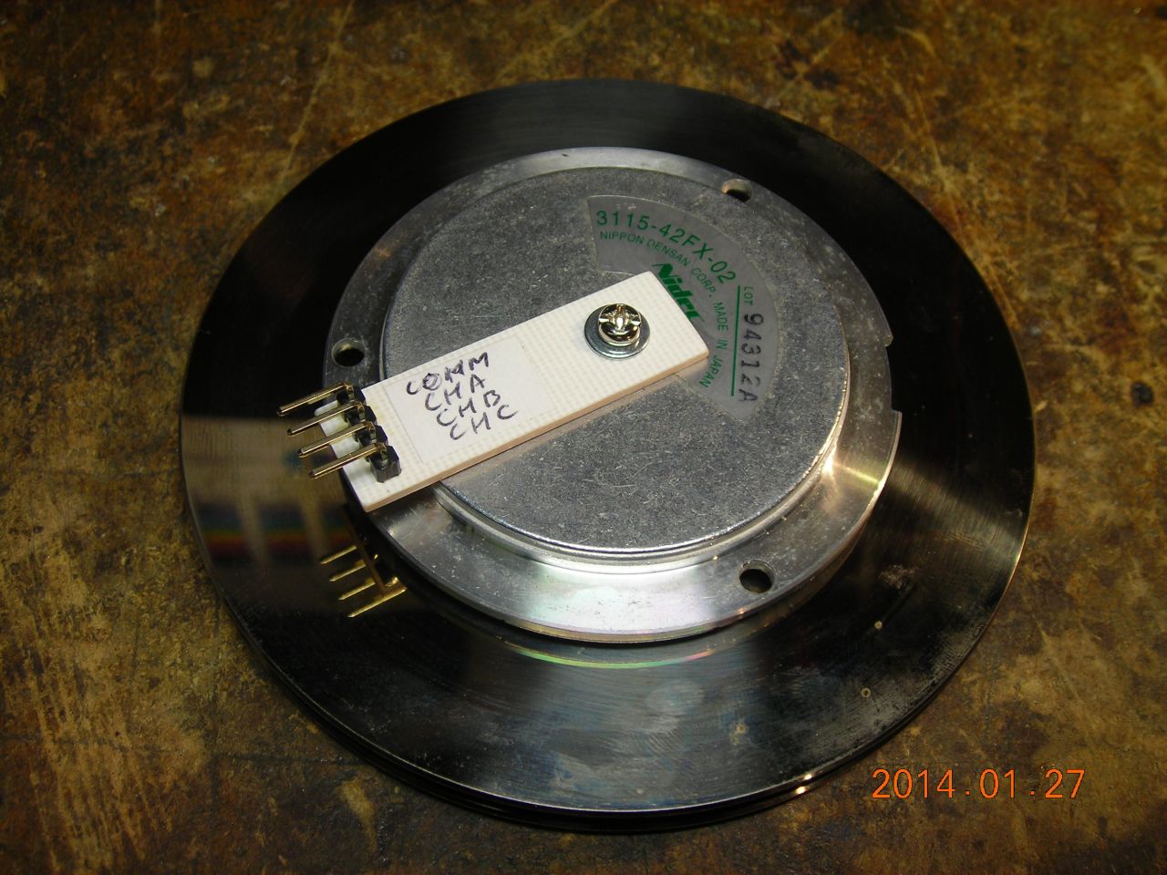
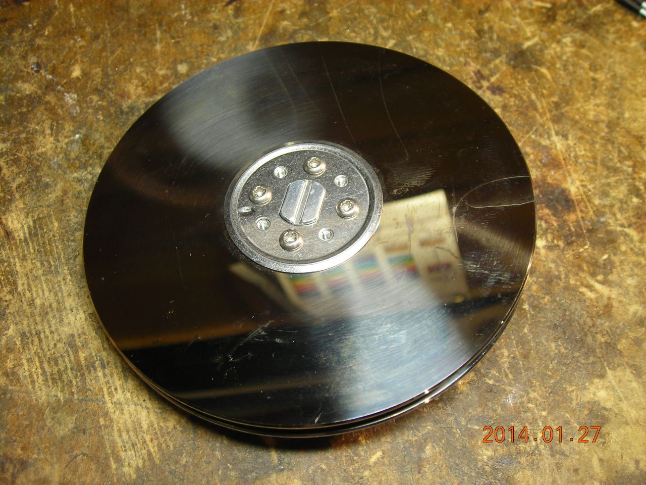
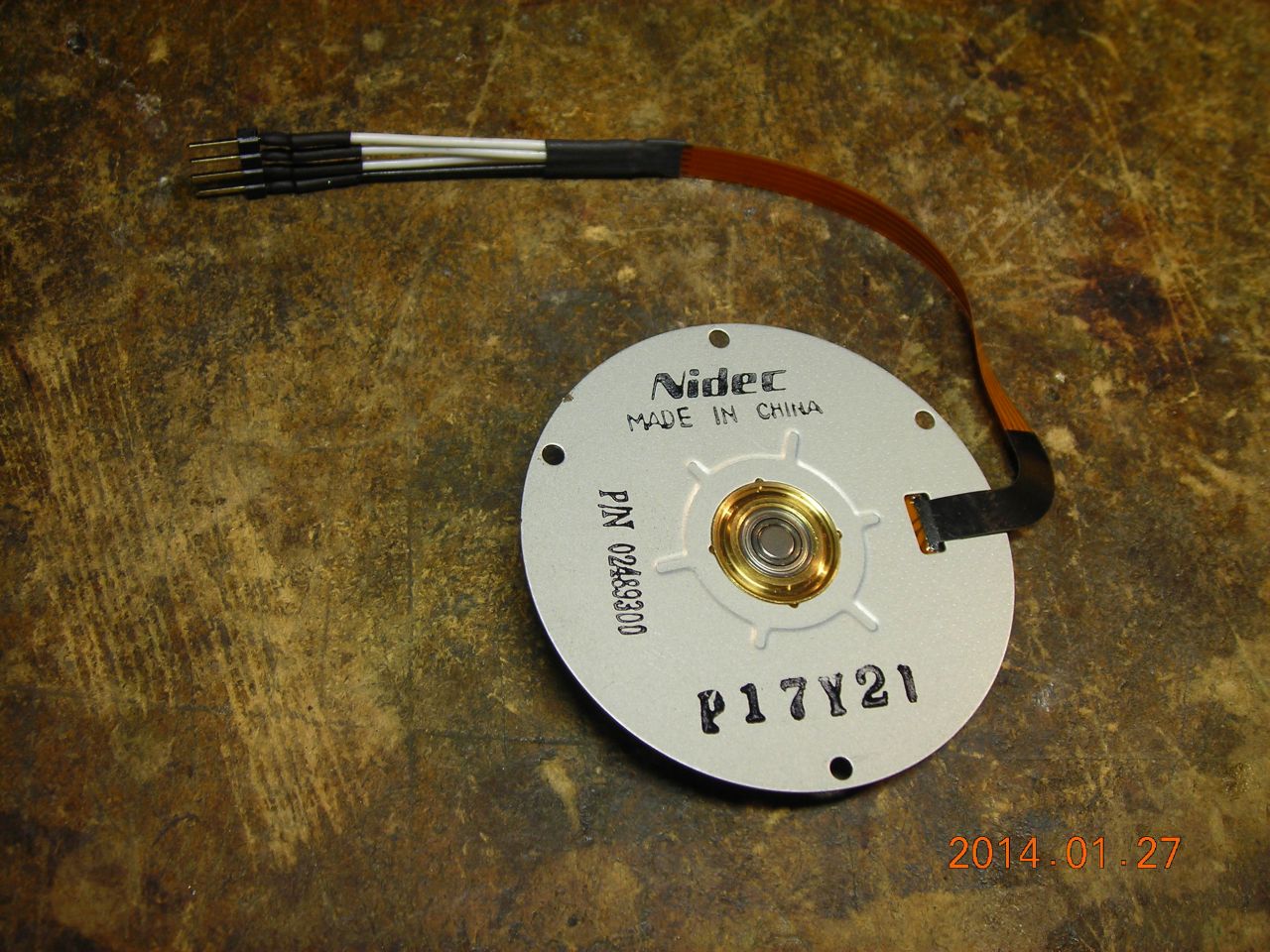
I came across several spindle motors in my scrap box in the attic - they're out of hard drives, floppy drives etc. The hard drive motors, in particular, are extremely smooth-running, and I wanted to see how to drive them.
They are all three-phase brushless, sensorless DC motors. The three coils are star-connected and a common is also provided, giving a total of four connections. Unlike brushless motors which use hall-effect sensors to detect the shaft position (and hence ensure correct commutation), the shaft position is sensed using the back EMF produced by the undriven coils. This technique is also used in RC model motors, although they usually just have three wires (no common). As a result, the motors sometimes spin a bit erratically at startup (sometimes even reversing) until the chip detects sufficient back EMF to "lock" on to the correct sequence.
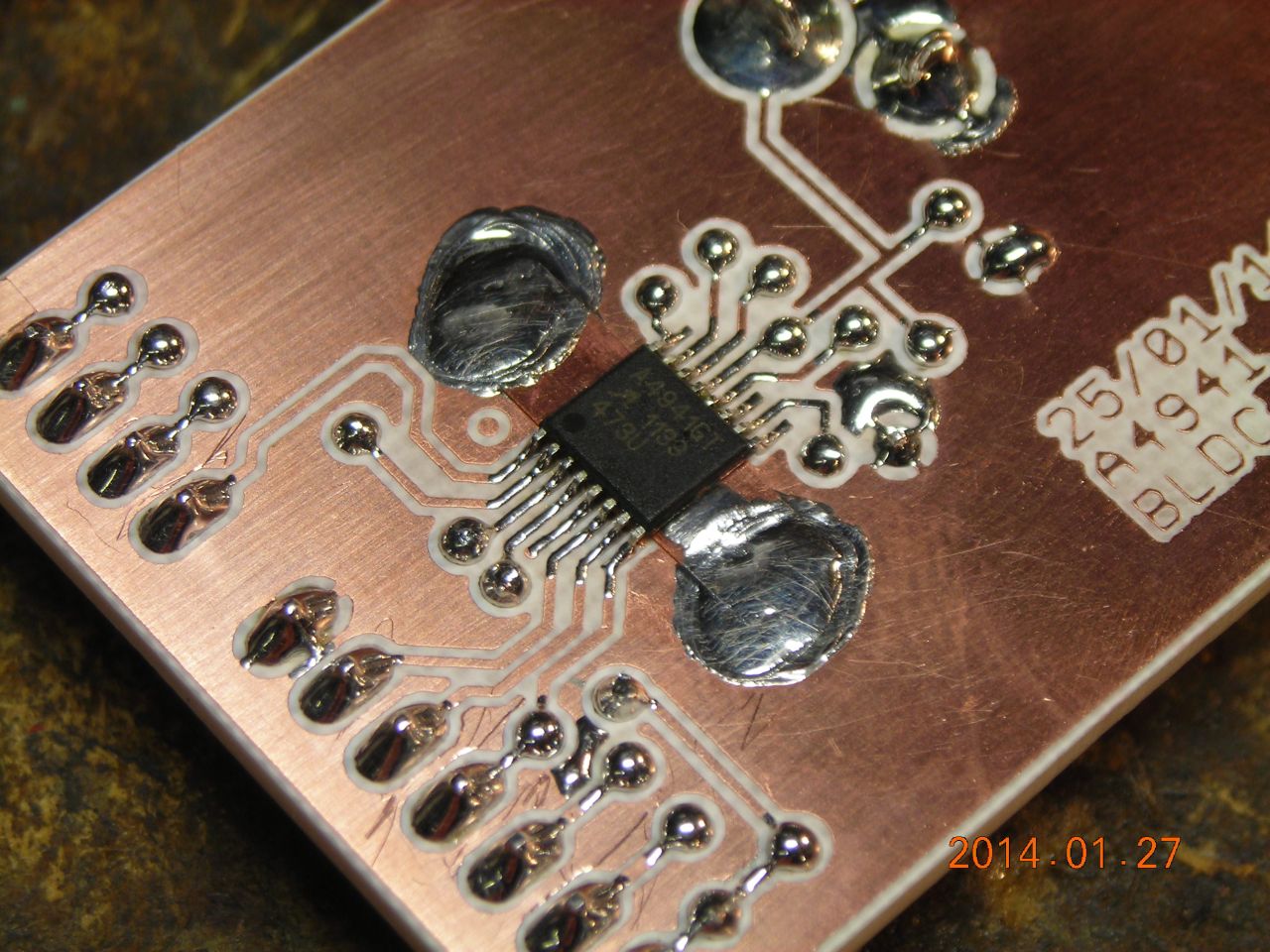
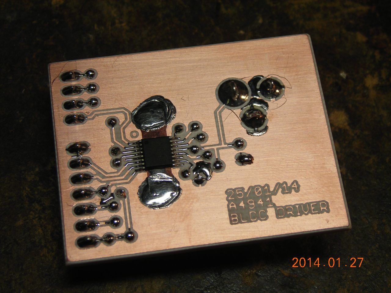
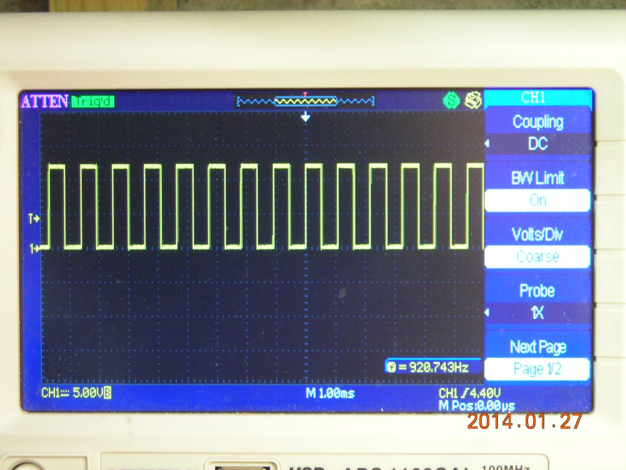
A wide range of brushless motor driver chips is available - some are sensorless, others require hall sensor feedback. Some have inbuilt push-pull drivers (to drive the motor directly), others require an external three-phase bridge. I eventually settled on the Allegro A4941, because it was available from RS. (RS are sometimes poor at stocking any of the interesting chips I want to play with!). This is a sensorless driver, intended for running fans, with up to 1.5A of output capability. Several external connections control things like fan speed (via PWM), soft switching and startup commutation time (how long the chip spends looking for a valid back EMF signal). It also provides an open-collector pulse output which can be used to monitor the motor's speed - for the motors I used here, I found that the pulse output was four times the actual motor rotational frequency.
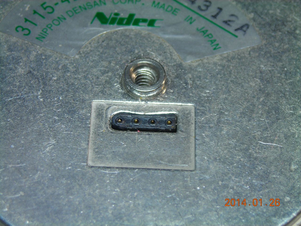
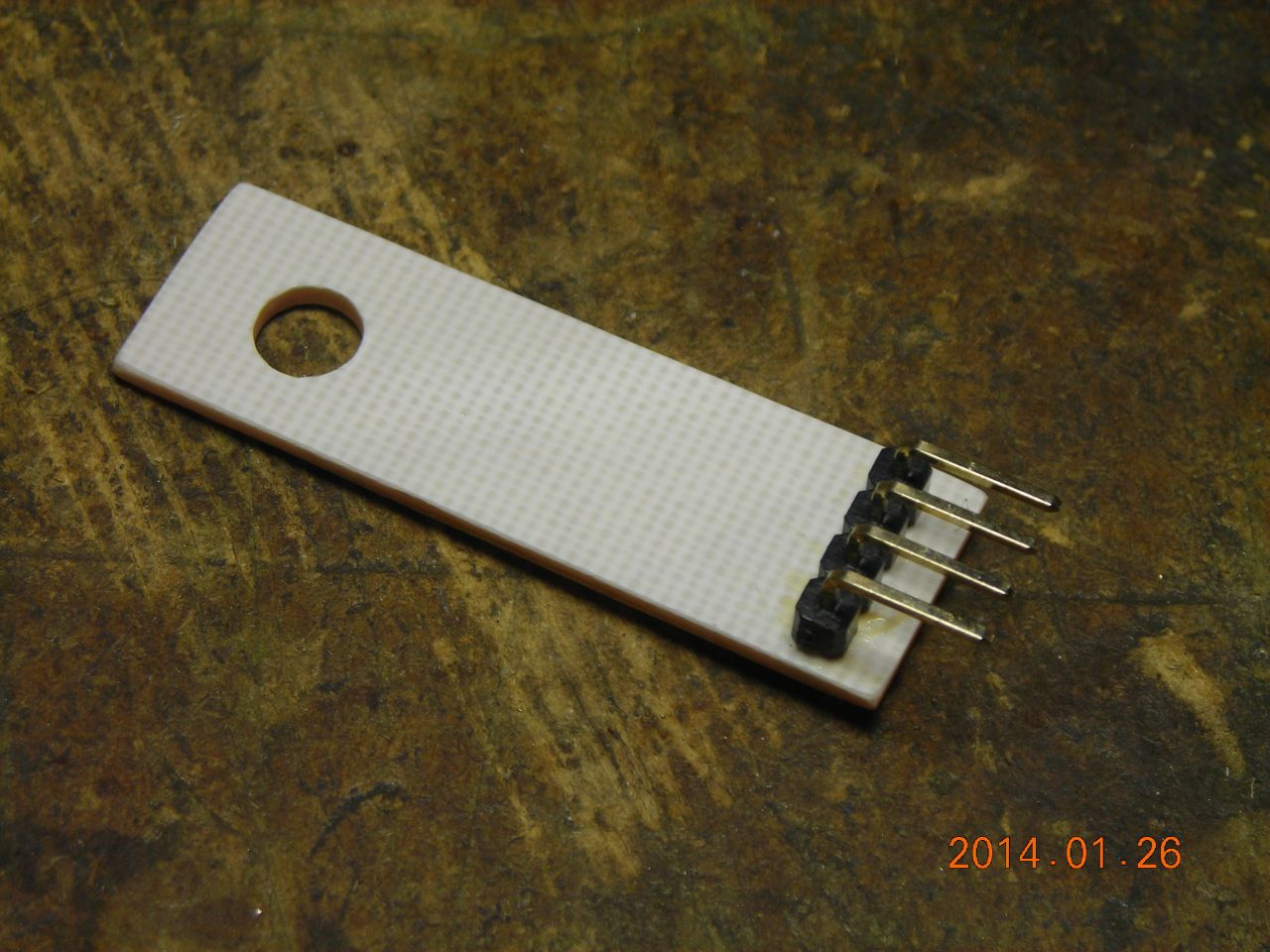
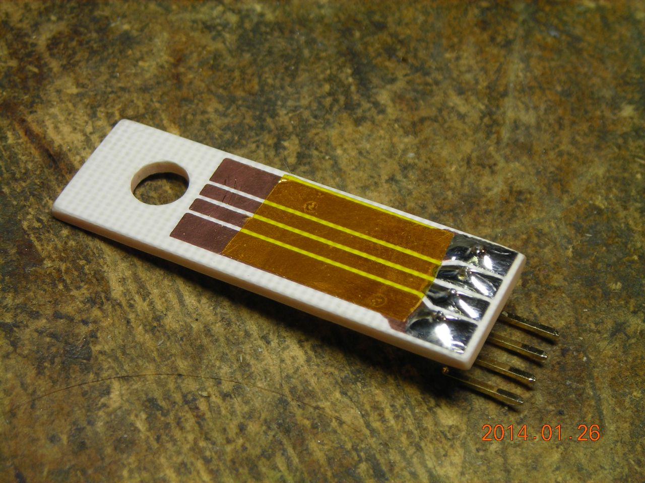
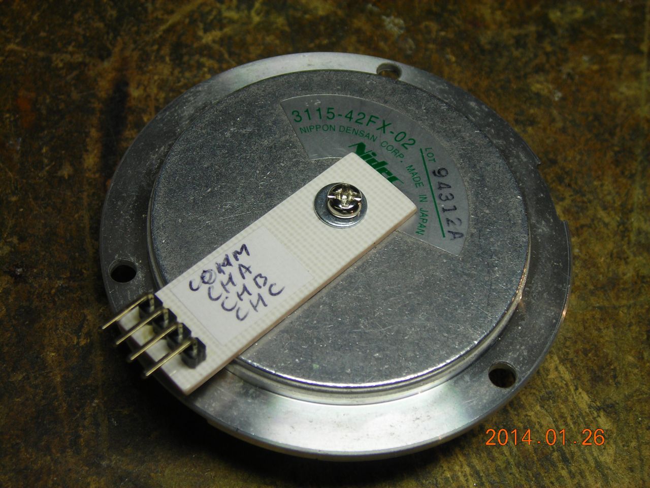
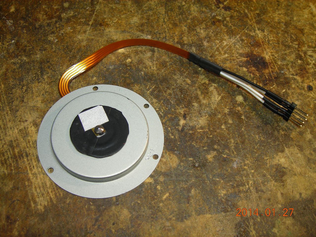
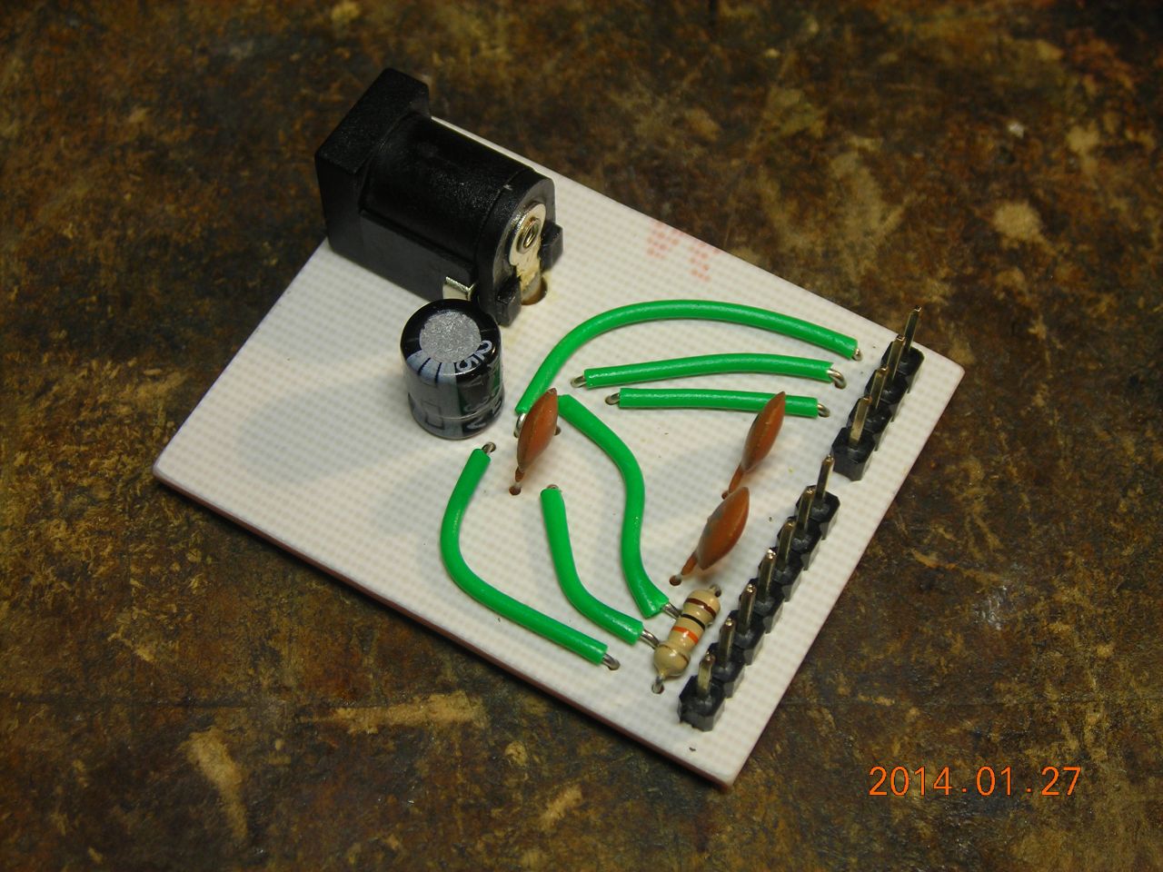
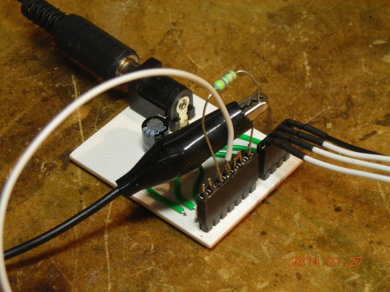
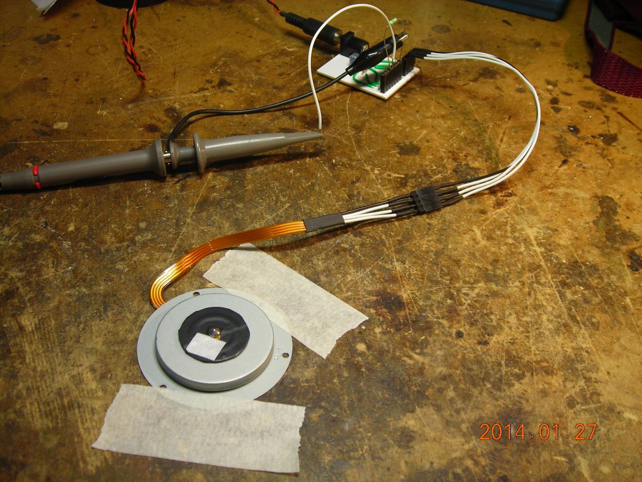
One of the motors I had (a hard drive motor) had little sprung plunger contacts on the back, so I made a simple "contact" board for it.
Here is a ZIP file with the PCB files, schematic, Eagle files etc. The chip has a thermal pad underneath for heat removal - I heatsinked this using a piece of copper foil soldered to the back, then to the PCB ground plane.
To find the motor pinout, measure the resistance between the various pins. When you have the common terminal, the resistance from it to each of the three others should be the same. To reverse the motor, it should be a simple matter of swapping any two of the phase connections.
The sense resistor used with the A4941 determines the current limit - I used 0.5Ω which gives about 400mA maximum current. This was insufficient for the larger hard drive motor, so I briefly shorted out the sense resistor during startup. See the datasheet for more info.
The motors all run pretty well - the hard drive motor is around 6000rpm with a 12V supply, and the ZIP drive motor is around 15000rpm (way too high for the original purpose!). You could in theory use the FG output to do closed-loop control of the motor speed using a separate microcontroller. There isn't much torque, which isn't surprising considering the small size.
Nidec make something like 60% of all drive spindle motors in the world, which is pretty impressive.
 |
 |
 |
 |
 |
 |
 |
 |
 |
 |
 |
 |
 |
 |
 |
 |
 |
Video of the motors running:
It's also possible to use the driver chips from the original hard disk PCB (to get an idea of the sort of chips used, this site has a listing of various driver chips with links to datasheets), but they are usually much more complicated since they often combine both the spindle motor driver and the voice coil driver (read/write head) into one package.
| ▲ Electronics |