| ▲ Electronics |
First, let's have a quick overview of the different inverter types, including voltage-fed/current-fed and half or full bridge.
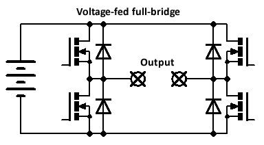
Here's a voltage-fed full bridge inverter. The full DC supply voltage can be applied in either polarity across the load, depending on which pair of switches is on. Antiparallel diodes should be used to clamp any reverse currents. There should be a small dead time between switching transitions to prevent shoot-through (where both upper and lower switches are on simultaneously, shorting the DC supply).
For lower powers, and to simplify the circuitry, a half bridge can be used instead. Here are two slightly different varieties. The first uses a pair of large smoothing electrolytic caps to clamp one side of the load to half the supply. The other side then swings between the negative and positive of the DC supply. Maximum voltage applied to the load is half the DC supply.
The second circuit uses a nonpolarised DC blocking capacitor (e.g. polypropylene film) to provide an AC output. This has some advantages - no need for large smoothing electrolytics, and one side of the load is referenced to ground, making sensing/driving requirements simpler. However, at low frequencies, the blocking capacitor becomes large.

These have all been voltage-fed inverters, which produce a squarewave output voltage across the load. These are far more common than their counterpart, current-fed inverters. However, current-fed inverters have some interesting features. Here's a current-fed full bridge inverter:
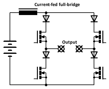
There are two main differences when compared with the voltage-fed inverter. A large inductor is placed in series with the supply. Instead of antiparallel diodes, you need to use series diodes to prevent current flowing in the reverse direction. Additionally, instead of a dead time (to prevent shoot-through in the voltage-fed inverter), you must use an overlap time, so that current is always flowing. If, at any time, current stopped flowing, the series inductor would produce a large spike, damaging components.
The net result is that a current-fed inverter outputs a squarewave output current. If the load is purely resistive, then things are essentially the same as a voltage-fed inverter; squarewave current, squarewave voltage. However, the situation becomes interesting with resonant loads, as described later.
Before moving on to resonant loads, here are the half bridge versions of the current-fed inverter:
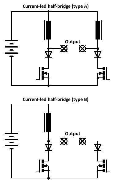
Although both produce the same peak-to-peak current across the load, the "A" configuration produces a symmetrical current waveform (swinging positive and negative), whereas the "B" configuration produces a unipolar waveform (swinging from zero to positive). According to this paper (Namadmalan, 2011), A is more suitable for induction heating and dc-ac converters, whereas B is more suitable for dc-dc converters.
We'll now have a look at the magnitudes of voltage and current in the different types of inverters.
Let's do some simulations in LTSpice to see what sort of V & I a current-fed inverter produces. (Voltage-fed inverters are less mysterious - they simply apply the full supply voltage for a full-bridge, or half the supply for a half-bridge.) I'll look at both resistive and parallel-resonant loads (the reasons for a parallel-resonant load will become clear later). Here's the component values used throughout:
The parallel-resonant load consists of a resistor (the simulated loss in the load) in parallel with the L+C combination:
The magnitudes of V & I are a little bit mysterious, so it's just simplest to simulate whatever circuit you're using.
Unsurprisingly, the inverter produces a 200V peak-to-peak swing across the load, with a corresponding 2A p-p current swing. This is exactly the same as a voltage-fed inverter. The current in the series inductor is 1A.
Things start to get interesting. The "A" configuration produces a symmetrical 400V p-p swing across the load (from -200V to + 200V) and a corresponding 4A p-p current swing. Current in each series inductor is 2A. However, the "B" configuration only produces a 200V p-p swing - in addition, this is unipolar, from 0V to 200V. The current in the series inductor is again 2A. Rather surprisingly, the voltage produced is greater than that from the full-bridge inverter - this is the opposite to voltage-fed inverters, where a half bridge produces a lower voltage (half) than the full bridge.
The inverter output current is squarewave, but the output voltage is sinusoidal (because of the resonant load). The peak-to-peak output voltage appears to be π times the DC supply voltage (in this case, 314V p-p). This factor of π does not depend on load resistance, driving frequency etc. The inverter output current will naturally depend on the load resistance - if we divide inverter output voltage by the current, both p-p values, we get a resistance which is about 1.26x the actual load resistance - whatever that factor means.
In both configurations (A & B), the p-p inverter output voltage is 2π times the DC supply. In the A configuration, the inverter current is symmetrical, but in the B configuration, it's unipolar. However, because the load is resonant, the inverter output voltage is always symmetrical about zero (and is always sinusoidal). If we again divide the p-p inverter output voltage by the current, we get a factor of about 1.26x the actual load resistance, although this seems to drop slightly at higher resistances. Note that the single inductor in the B configuration has to carry twice the current than each of the inductors in the A configuration - a totally different behaviour to the resistive load example.
| Output V p-p as multiple of DC supply | Comments | |
| FB - resistive | 2 | |
| FB - resonant | π | |
| HB - resistive | 4 | B config - unipolar V and I |
| HB - resonant | 2π | B config - unipolar I |
So - why are current-fed inverters so good for induction heating power supplies?
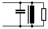
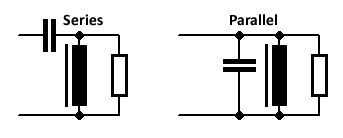
Induction heater tank circuits are either series or parallel resonant (there are more advanced types, such as LLC, but don't bother with that). The loss produced by the workpiece in the induction heating coil can be represented by a resistor in parallel with the inductor.
Here's some discussion on the benefits of current-fed inverters.
It would intuitively be desirable that a resonant tank should draw less current when the tank is unloaded (i.e., the workpiece removed/empty coil). Series and parallel resonant tanks exhibit very different behaviours, as explained below.
In a series-resonant tank, the impedance of the tank circuit reaches a minimum at the resonant frequency. Resonance is damped by the presence of a load (i.e. the existence of a parallel loss resistance). A reduced load leads to reduced damping and a corresponding reduction in impedance. Therefore, an unloaded series-resonant tank circuit will draw more current from the inverter, assuming the applied voltage is kept the same. Therefore, some means of active power control (to reduce the applied voltage in an unloaded situation) is essential to prevent current from exceeding safe limits. Note that this is not always the case - some applications always have a load present, e.g. rice cookers - but these examples are in the minority.
By contrast, a parallel-resonant tank reaches a maximum impedance at resonance. Theoretically, a pure LC parallel tank will have an infinite impedance, but this is reduced by the presence of the parallel loss resistance. Decreasing the load on the coil (e.g. removing the workpiece) increases the impedance and hence reduces the current draw. Therefore, no active power control is required! Parallel-resonant tanks are far better.
Let's suppose, for sake of argument, that you tried connecting a voltage-fed inverter to a parallel-resonant tank. The inverter outputs a squarewave voltage waveform. This has harmonic components at multiples of the fundamental frequency. Since the tank capacitor is connected directly across the inverter output, and since the capacitor's impedance decreases with increasing frequency, large currents will flow at the harmonics of the main inverter output, possibly damaging the inverter switches. This is why only series-resonant tanks can be used with voltage-fed inverters, since they present a rising impedance at higher frequencies.
A parallel-resonant tank can only be driven by a current-fed inverter.
It's possible to use the series inductor as part of a buck converter circuit, as shown below:
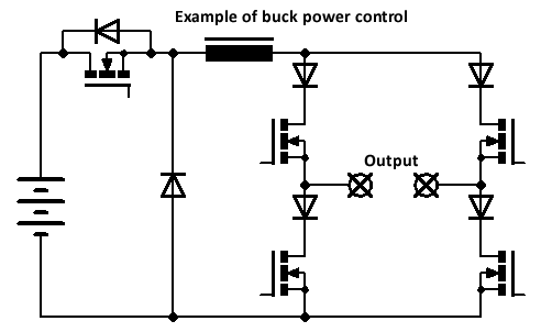
I first found out about this approach in one of Inductotherm's patents. It works extremely well, and gives smooth, instant power control over the whole operating range.
This one is perhaps not entirely unique to current-fed inverters, but I think it might be. The output voltage of a current-fed inverter is always "large" even if there is no load present. This makes the tank voltage very easy to sense, either directly or through a transformer (plus suitable division/clipping to bring it down to a safe level). By contrast, the output current of a voltage-fed inverter drops as the load is reduced, making it difficult to sense reliably over a wide range of loads. For a reference signal, we can simply use the drive signal to the inverter and delay it slightly to account for the delay time through the gate drivers and switches.
Some time ago, I put all of this into practice and built a current-fed induction heater for a graphite crucible. It used a buck power control technique, with feedback taken from the tank coil using a coil of wire wrapped along with the copper tubing. The tank coil (and hence load resistance) was sufficiently large that the inverter could be run directly from the mains, with no need for a matching transformer. I used a proper Celem conduction-cooled capacitor for the tank. The whole thing worked perfectly, running from a 120V isolation transformer - I was heating tin cans red-hot, and melting some lead in the crucible. However, when I tried operating it on full 230V mains, something obviously very bad happened, and I blew every single MOSFET in the buck converter, the inverter, the gate drivers, and some other stuff as well. I never had the heart to repair it, so the remains are still sitting in a box in the garage.
There's a Flickr set here with some photos of what it looked like. I think what happened was the series inductor saturated (I didn't fully understand how to wind big inductors reliably at that point) and that proceeded to fry everything else. Once I make some sort of fast electronic breaker, I might re-attempt it again!
| ▲ Electronics |