| ▲ Mechanical |
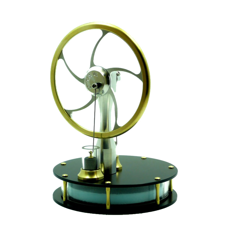
I originally had a little low-temperature-difference (LTD) Stirling engine that would run from a cup of hot water or even from body heat. The big engine shown here is pretty nearly a 2:1 scale version of that small engine. The small engine was very similar to the Kontax KS90, some photos of which are shown below for reference (these are from Kontax's site at http://www.stirlingengine.co.uk).
 |
 |
 |
 |
 |
The first thing you realise upon looking at the Kontax engine is how finely balanced and low-friction everything is. I was a little apprehensive about whether it would be possible to simply scale the parts up and still get them to work smoothly. As it turned out, everything worked fine in the end.
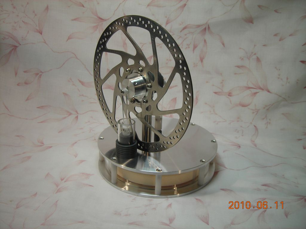
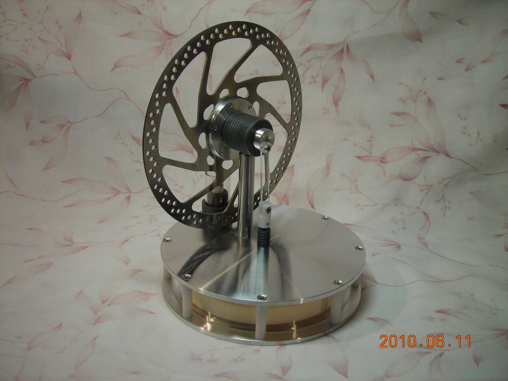
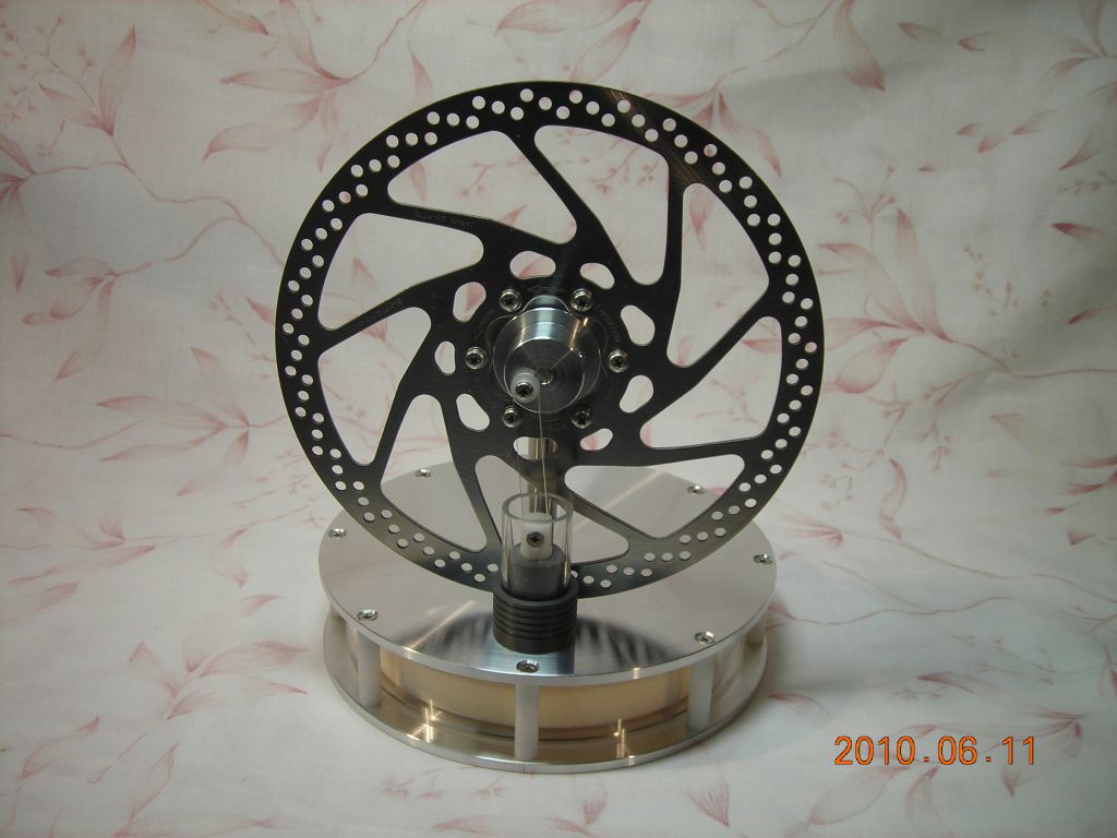
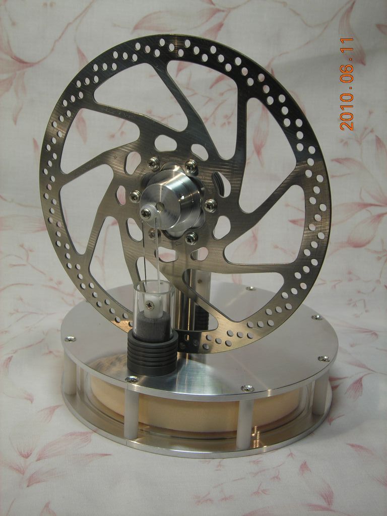
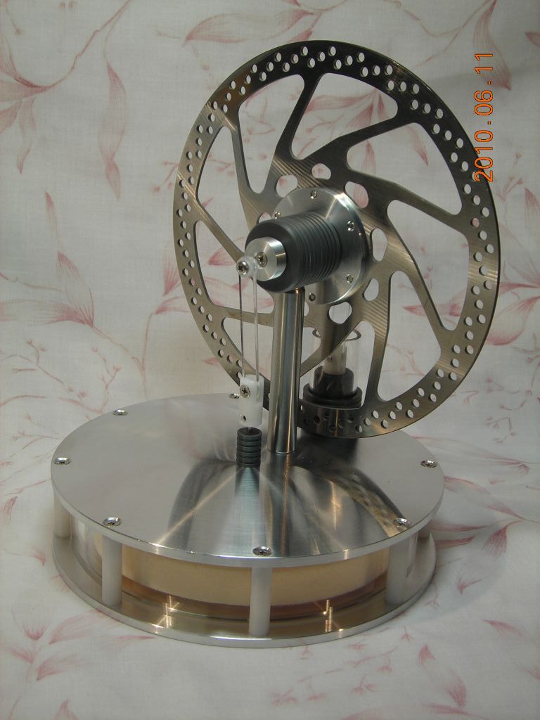
Photos of the large engine are shown below. There aren't any drawings for this, unfortunately, because I made up the measurements as I went along!
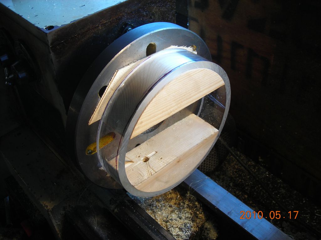
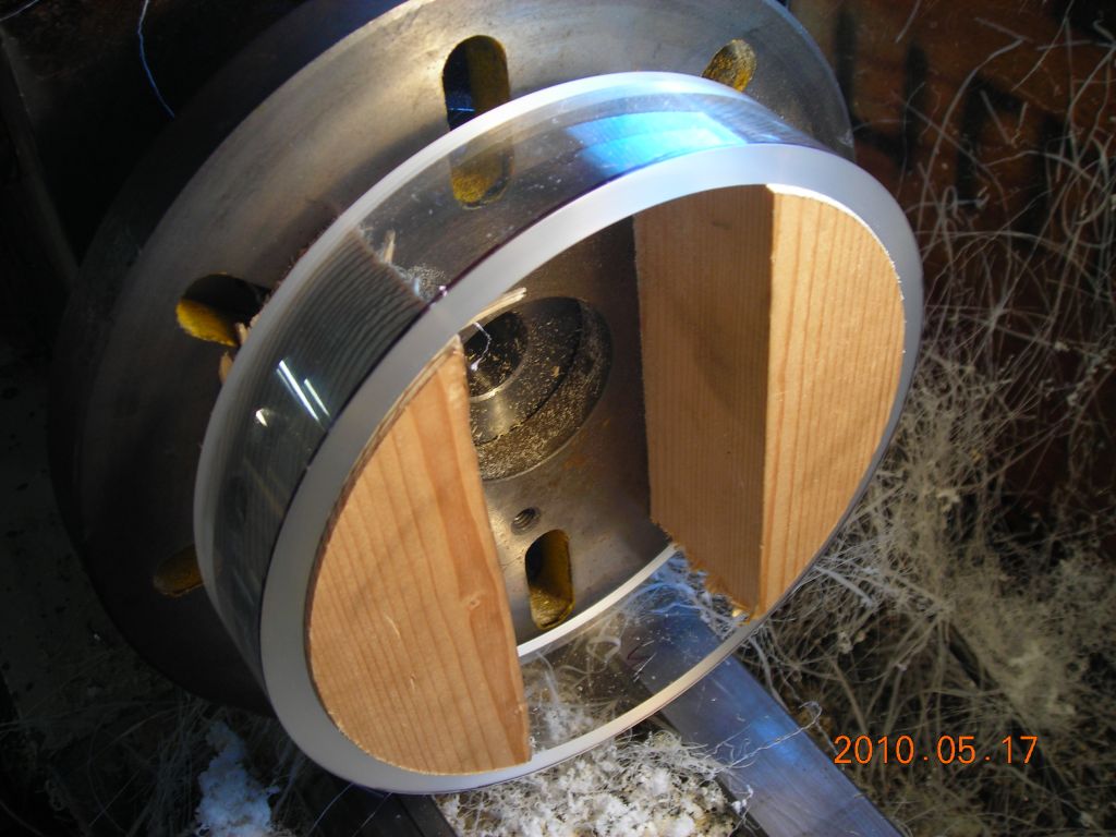
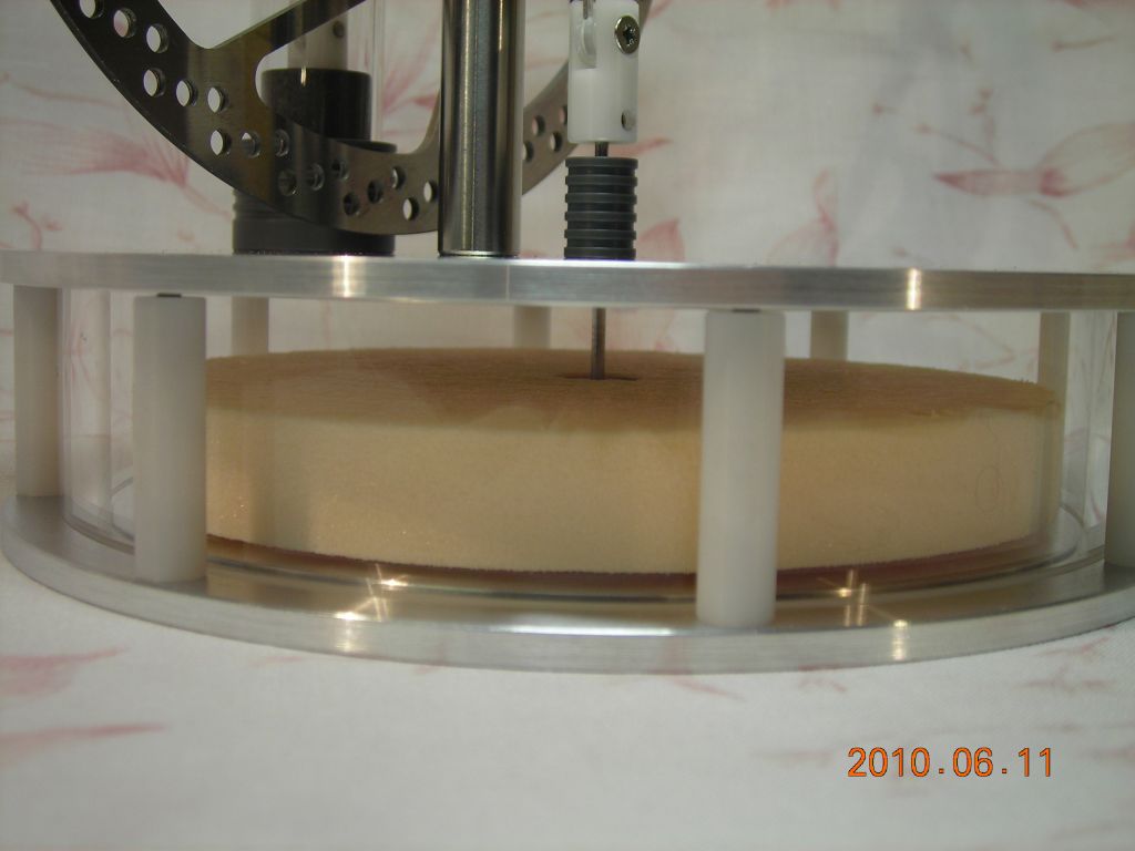
Displacer cylinder and plates The displacer cylinder is machined from 6" diameter, ¼" thick acrylic pipe. Holding this true in the lathe presented some difficulties. I eventually screwed two blocks of wood to the faceplate and turned them down until they were a neat fit inside the pipe. I then shoved a rough-cut piece of pipe on and turned both ends without moving the pipe. This ensured that both ends were exactly parallel.
The end plates were turned from some 5mm aluminium plate I found in a skip. There is a small spigot turned on each so they locate nicely inside the displacer cylinder. The aluminium was the softest, crappiest stuff I've ever used, but I managed to get a decent finish on it with plenty of sandpaper. The two endplates are clamped together with M3 countersunk screws which go into a Delrin insulating spacer to prevent heat conduction.
Displacer and connecting rod The displacer itself is turned from a piece of building foam (the dense, closed-cell stuff). A plastic bush is pressed into the middle of this and the displacer connecting rod is screwed into the bush. To reduce friction, the bearing for the displacer rod is made from a small piece of graphite held in a plastic housing. The connecting rod is laser-cut from 2mm acrylic sheet and pivots on small nylon bushes to reduce friction.
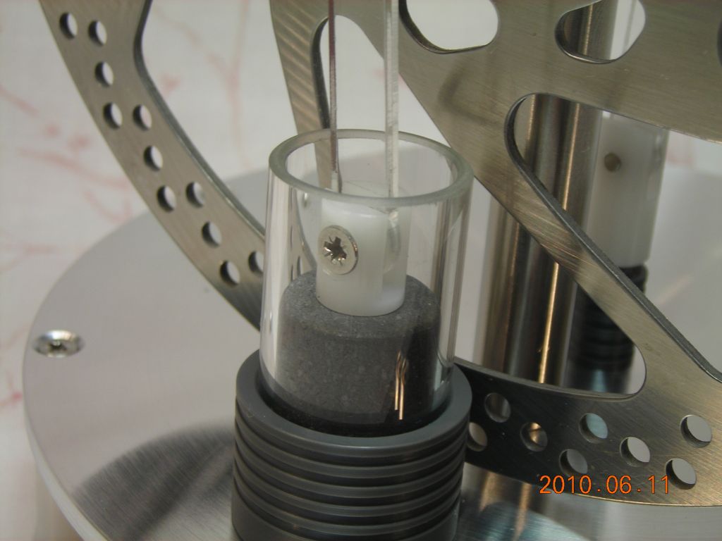
Power cylinder and piston The cylinder is made from a short piece of borosilicate test tube glass. It was rough-cut by hand and then ground to exact length/squareness on the lathe using a diamond burr mounted in a Dremel tool. Since the glass is quite cheap, it's not perfectly round, and there is some leakage round the sides of the piston. For the ultimate cylinder, it would be best to cannibalise a ground-glass gas syringe, since they are bored perfectly cylindrical.
The piston is turned from a chunk of graphite, hacked off my massive block of graphite I keep in the shed. A small plastic clevis fork is screwed into the piston, and this attaches to the connecting rod. Another small nylon bush is used as a pivot.
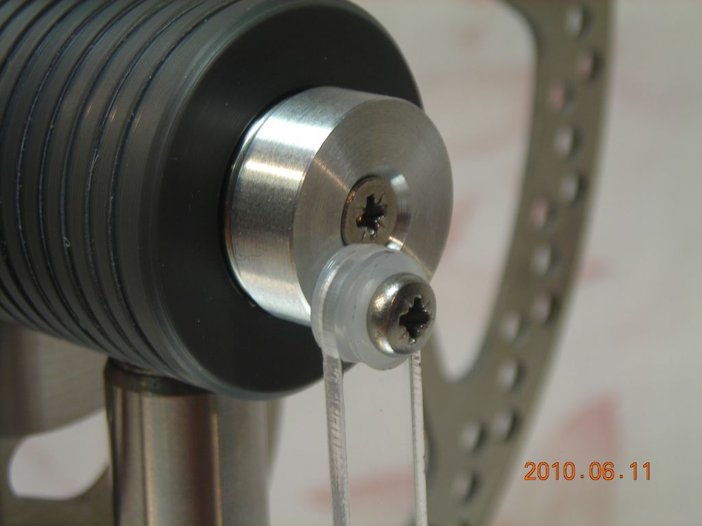
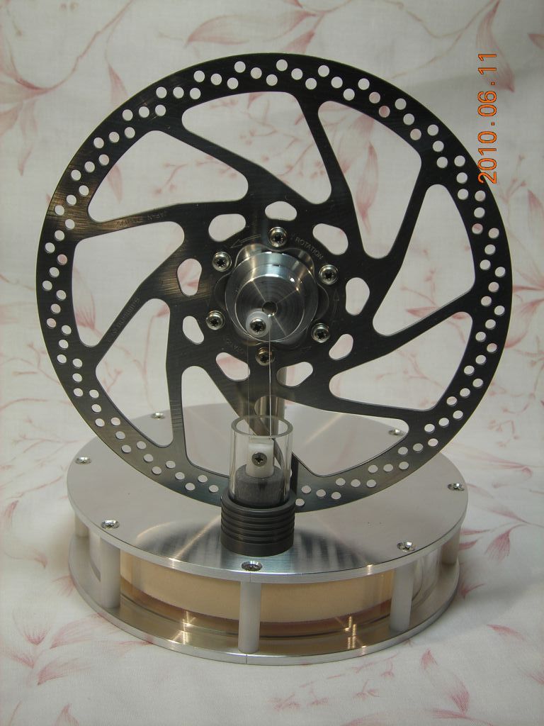
Crankshaft and flywheel I finally found a use for all the stepper motors I keep hoarding - once pulled apart, they provide a nice shaft and pair of ball bearings. These were used for the crankshaft. The ball bearings were mounted inside a PVC housing which was then mounted on a Thorlabs ½" optical post to support it. The flywheel is actually a bicycle disk brake - the technician at uni thought on that, and it's an absolutely brilliant idea. This was a scrounged one, but they're only £15 or so to buy new. It's screwed to an aluminium hub which is attached to the crankshaft. I was extremely pleased when the flywheel ran true!
 |
 |
 |
 |
 |
 |
 |
 |
 |
 |
 |
 |
 |
 |
 |
 |
Here's a video of the engine running from a dish of boiling water. The engine runs really smoothly, and will work in both directions (after reversing the phasing of the displacer).
I realised that it would be difficult to scale this sort of engine up any further without some trickery, as the weight of the displacer becomes signifcant. As the engine is running, you can see it slow down as the displacer is being lifted. At larger sizes, this would eventually stop the engine. Some sort of counterweight would be needed to offset the weight of the displacer. It's probably doable.
| ▲ Mechanical |