
| ▲ Optical |
First, some background links. I originally saw a posting on Hackaday (http://hackaday.com/2013/12/16/reverse-engineering-a-candle-flicker-led/) where a guy (http://cpldcpu.wordpress.com/2013/12/08/hacking-a-candleflicker-led/) had analysed the waveform from a flicker LED and produce an algorithm for reproducing the random sequence.
Evilmadscientist (http://www.evilmadscientist.com/2011/does-this-led-sound-funny-to-you/) also looked at these a while ago. Interestingly, the LED they had used a controller chip with extra (unbonded) pads, suggesting it had other functions. A common ploy seems to be to use a melody generator IC to power the LED - here's one which plays Für Elise - http://www.instructables.com/id/Listen-to-a-led-tea-light/.
User "natecaine" (http://hackaday.com/2013/12/16/reverse-engineering-a-candle-flicker-led/#comment-1144854) posted a great macro shot of the controller die on Hackaday, with a detailed analysis of the layout. This is also shown in a later Hackaday posting - http://hackaday.com/2014/03/02/reverse-engineering-candle-flicker-leds-again/.
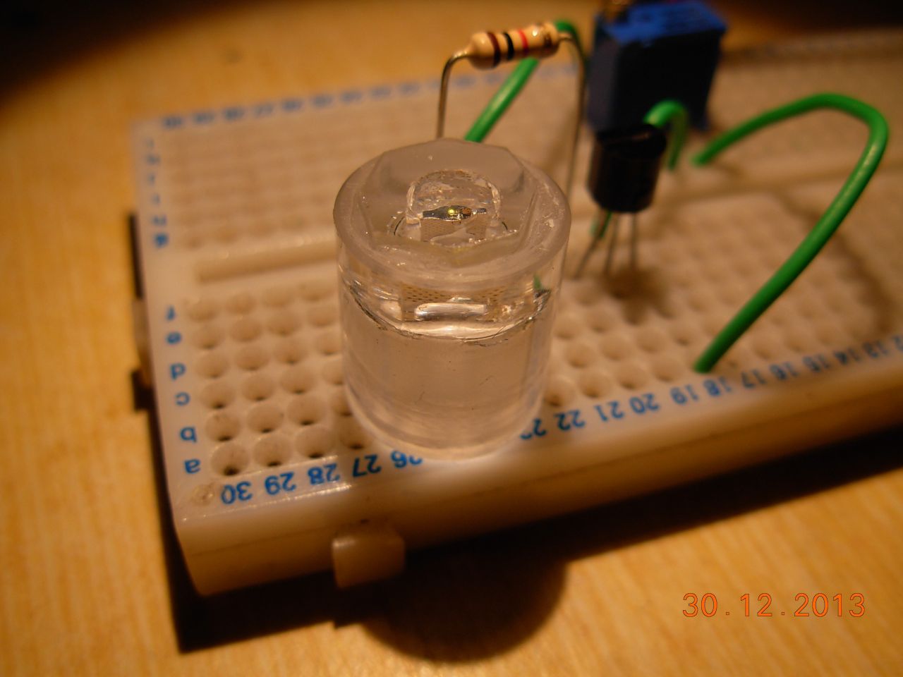
Naturally, I was curious to see for myself, so I managed to get hold of some yellow flicker LEDs from Lighthouse LEDs in the USA (http://lighthouseleds.com/5mm-yellow-gold-candle-flickering-led-super-bright.html). To get a clear view inside, I glued the LED into a piece of acrylic rod, then turnded and sanded the front flat to within maybe 1mm of the die, then superglued on a piece of microscope slide. The superglue helps to eliminate the effect of the rough plastic.
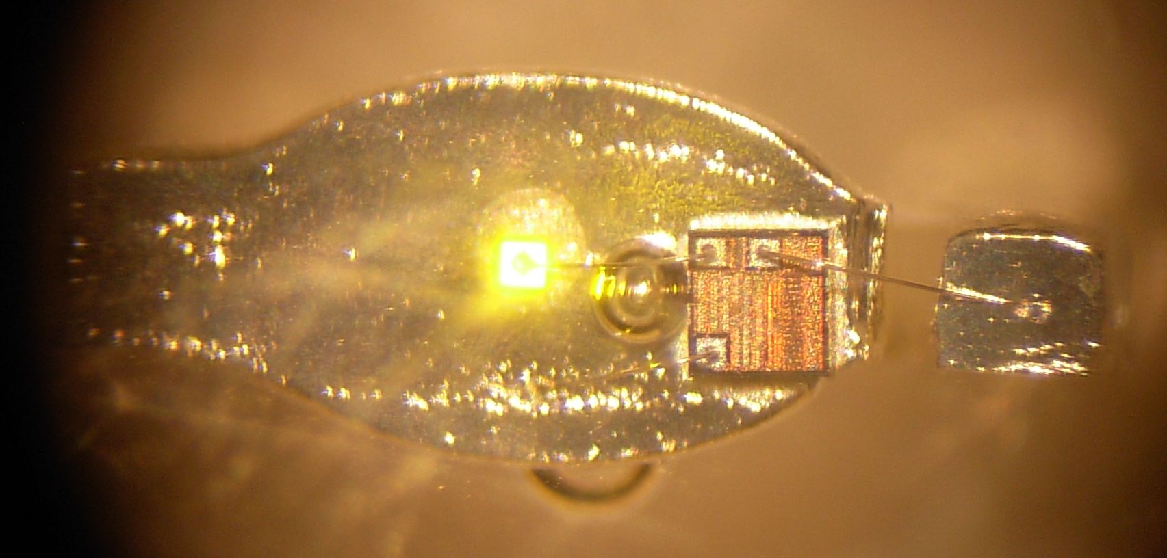
Here's some photos, the last one down a microscope. I was a bit disappointed to see that the chip only has the expected three connections - no mysterious extra pads to play with. The large spherical thing between the LED die and the controller chip is actually a bubble in the epoxy - you can see another one towards the bottom of the image.
 |
 |
 |
Video down the microscope showing flicker operation:
I subsequently messed around trying to analyse the waveform, but didn't really get anywhere meaningful - as expected, there were a dozen or so discrete PWM intensities which were chosen at random. I measured the voltage across the sense resistor using the computer's line in audio input (with a suitable divider), recorded it with Audacity, exported as RAW 32-bit floating point data, wrote a little C program to look for threshold crossings and work out the PWM period and high time, then plotted it all. To be honest, I can't be bothered writing about the whole process since it didn't really show anything more than what's already been found! If you're really interested, drop me an email and I'll explain. The audio wasn't even of the musical variety either, unlike some of the flicker LEDs going about.
| ▲ Optical |