| ▲ CO2 laser cutter |
Before the laser cutter can do anything, the laser beams must be accurately aligned to the motion of the two axes. Otherwise, the beam won't hit the centre of the focussing lens and things simply won't work.
I have tried to explain here, in as much detail as possible, the technique I use for doing this. Apologies if it seems long-winded and I repeat myself, but I want to make things clear.
Before proceeding with this, I would highly suggest modifiying the mirror mounts (as described elsewhere) - it will make adjustment a lot easier.
As part of the alignment process, you will need to find out where the laser beam is striking. There are two ways of doing this. Either you use the laser beam to make a small char mark on a piece of ordinary paper, or use the laser beam to heat some thermal fax paper and turn it black. I'll discuss the merits of both of these.
Ordinary paper. The laser power is reduced sufficiently so that, when a piece of ordinary paper is placed in the unfocused beam (i.e. direct from the laser) a char/burn mark appears slowly over the course of several seconds. This allows you to just mark the paper and no more. This is fine, but you must NOT do this when the piece of test paper is near (less than an inch or so) a mirror or lens surface! As the paper chars, steam and fumes are often ejected from the back of the paper and will mark the mirror. It can be cleaned, but why run the risk? So, if you must use ordinary paper, and are working near a mirror mount, remove the mirror first to avoid damage.
This is in fact how the rear mirror in my laser was damaged at the factory - they had placed a piece of sticky tape over it and burned a hole in that with the laser!
Thermal fax paper. This is the paper which is normally white, and turns black when exposed to moderate heat. It used to be widely available for fax machines, but now it's used more in tills, cash registers etc. It has the enormous advantage that, unlike normal paper, there is no charring or burning involved in the marking of the paper. Again, the laser is turned down low enough so the power is just enough to mark the paper. You can use thermal paper near a mirror mount when the mirror is in place. I would still obviously not place it directly on the mirror's surface, but you can use it very close (1/4") to it.
Now, unlike normal paper, it's harder to distinguish succesive laser strikes with thermal paper. Normal paper gets progressively darker brown as the laser is fired repeatedly, but thermal paper just stays black (until you actually burn through the paper)
My best suggestion. Use normal paper to align the laser beam with the mirrors removed. Then, once the beam is aligned, insert the mirror in question and use thermal paper to check the beam is striking it centrally, and isn't hitting the mount etc. I'll describe this as we go through the alignment process.
Here is a diagram of the light path in the cutter, with the various components indicated (click for a large version):
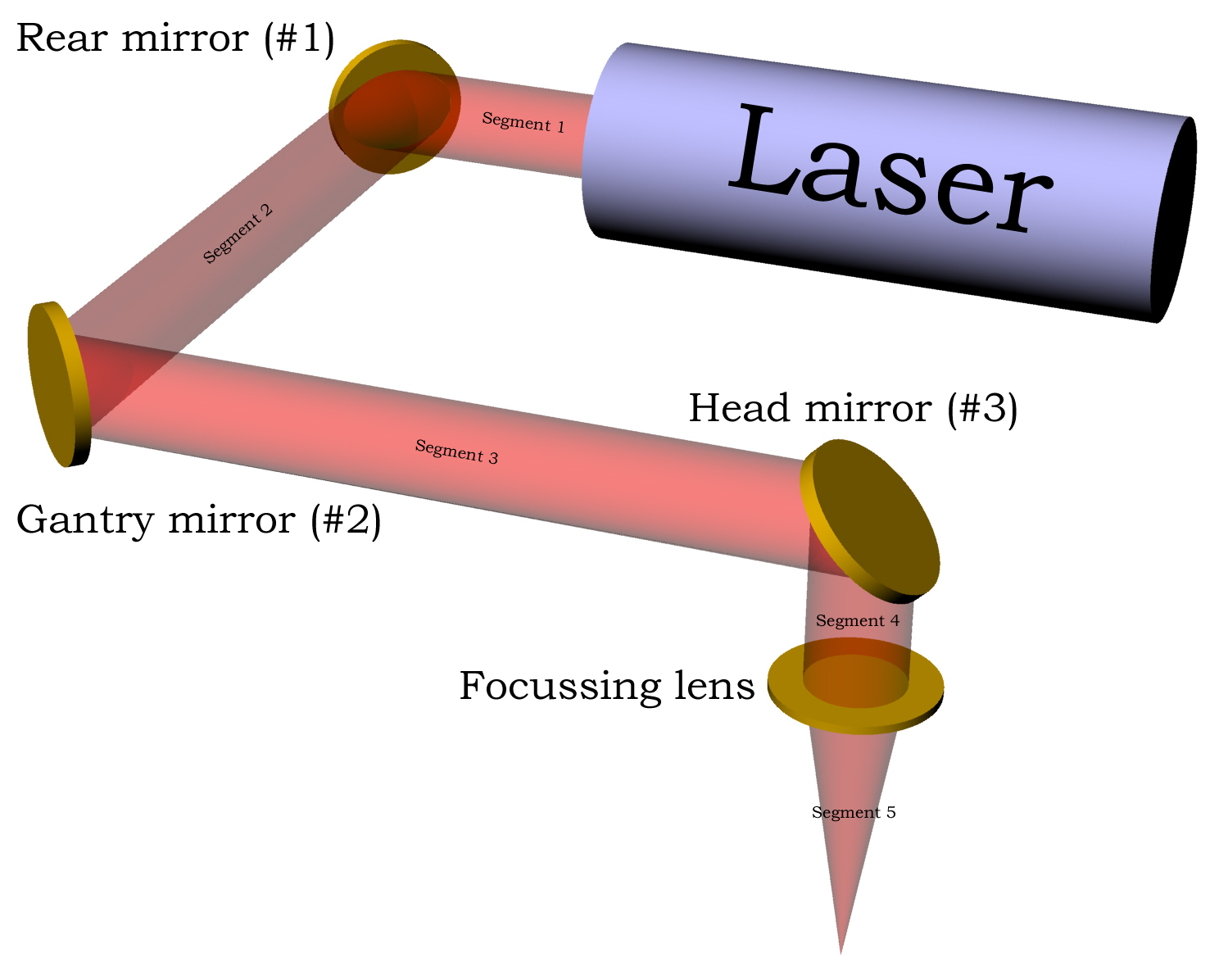 |
We'll define the X axis as left-right, and the Y axis as front-back. The laser head, which carries the head mirror (#3) and the focussing lens, moves back and forth in the X direction along the gantry, which in turn moves back and forth along the Y direction and carries the gantry mirror (#2).
There are a total of five segments to the light path:
The following conditions must be satisifed for the light to travel properly to the focussing head:
Criteria 1 & 2 ensure that the laser beam always enters the cutting head, no matter where the head is located on the work table.
I will now describe briefly what has to be done to achieve all of these criteria.
Criterion 1. The rear mirror (#1) is adjusted to deflect segment 2. By moving the gantry back and forth in the Y direction with a piece of detection paper attached, we can get segment 2 parallel to the Y axis.
Criterion 2. Similarly, the gantry mirror (#2) is adjusted to deflect segment 3. By moving the head back and forth in the X direction with a piece of detection paper attached, we can get segment 3 parallel to the X axis.
Criterion 3. There is nothing we can actually do to ensure this is the case. The direction of segment 4 is determined by the head mirror (#3) which is not adjustable. It is fixed rigidly to a mount machine at 45°. However, the path distance to the table is relatively small (~5cm) and constant, so this is not too critical.
Criterion 4. This would normally be achieved by translating the focussing lens in the X-Y plane until the beam passed through the centre. However, this is not possible. We can translate the head assembly in the Y direction by loosening the 3 screws on top of the plate, but we cannot move the lens in the X direction. Instead, we have to bodily raise or lower the laser beam in segments 1, 2 & 3 to achieve the same effect. For example, if the laser beam was raised, it would strike the head mirror (#3) higher, and reflect on to the lens in a position more to the left of centre (and vice versa). The only way we can raise or lower the laser beam is unfortunately to raise or lower the laser tube itself! This is awkward, because we can only tell if it's hitting the centre of the lens once we've aligned the rest of the beams. So we then have to go back and start again.....
OK, that's the brief description. Now I will go through each of these and give a detailed desription of how to do them. There is no detailed description of criterion 3 because, as explained, nothing much can be done about it.
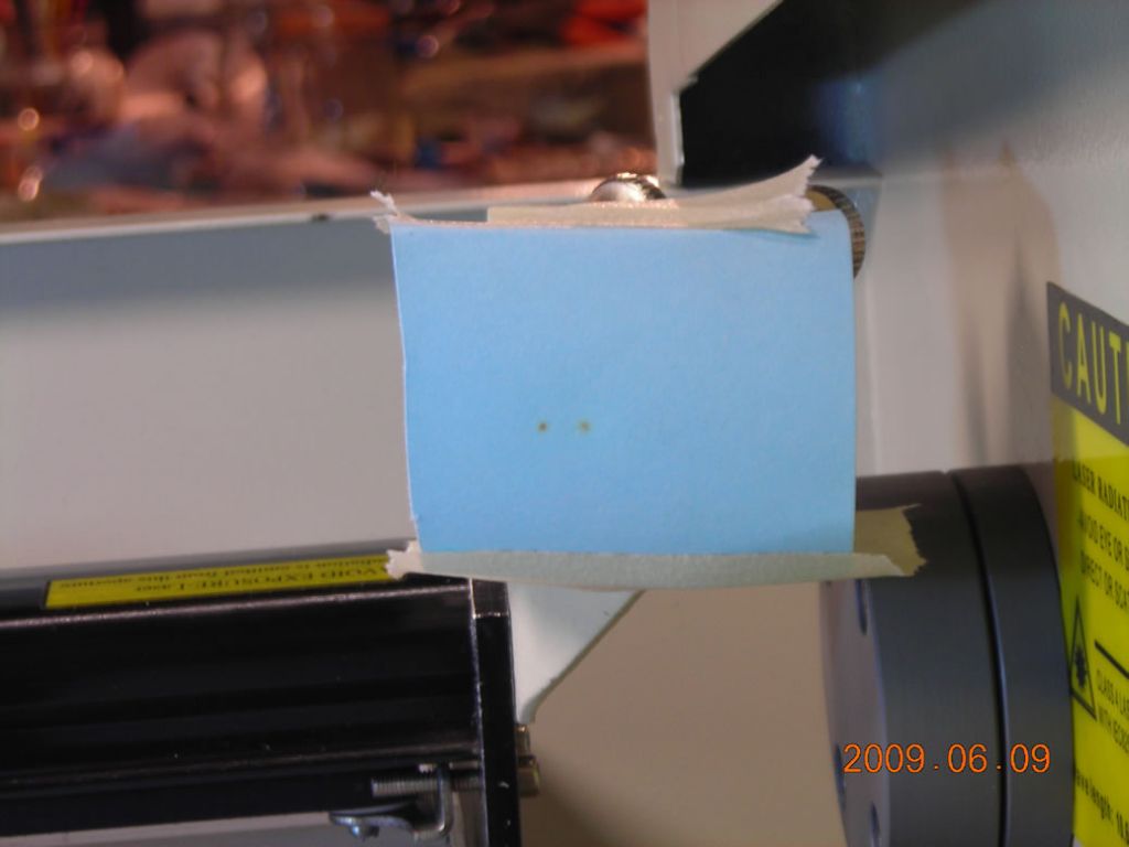
First, ensure that the laser beam from the tube strikes the rear mirror (#1) somewhere in the centre, and reflects off it without striking the mirror retaining ring. Do this by placing a piece of thermal paper over the mirror and firing the laser. The photos below show before & after. If the beam isn't in the middle, you can slide the mirror mount back-front, and you can also raise & lower it. At this stage, do not adjust the height of the laser tube; that comes later.
 |
 |
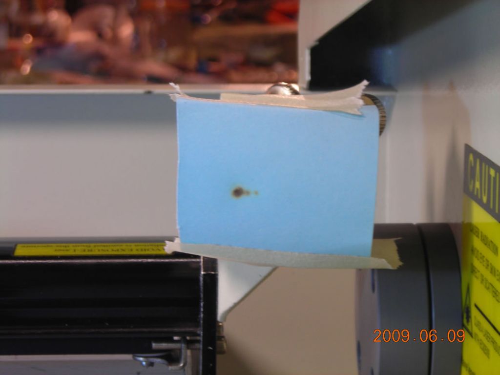
Now, make sure the mirror in the gantry mirror (#2) is removed. Tape a piece of paper over this so the laser beam reflected from the rear mirror strikes it. Move the gantry to the rear and fire the laser. Now move the gantry to the front and fire the laser again. Unless you were extremely lucky, you will get two burn marks on the paper. This shows that segment 2 isn't properly aligned. The photos below show the marks with the gantry at the rear and at the front. You can see the two small brown marks.
The left mark was obtained at the rear, the right mark at the front.
 |
 |
With the gantry in the front position, adjust the rear mirror (#1) to place the burn mark over that obtained when the gantry was at the rear. The photo below shows this happening. When you think you're close, stick on a fresh piece of paper, move the gantry to the rear, fire laser, move gantry to front, fire again, and see how close you are this time. Iterate this process a couple of times and eventually the burn mark will be in exactly the same place both front and back.
 |
You should really just play around with the mirror mount for a while to get a feel for the sensitivity and directional movement.
Once you have segment 2 aligned with back-front movement, you can now place the mirror into the gantry mount (#2) and again use thermal paper to check the beam strikes the mirror and doesn't hit the retaining ring.
No photos this time. The procedure is exactly the same as for segment 2, though. This time, place a piece of paper on the head itself. Move the head to the left, fire the laser, move the head to the right, fire the laser again. You will again have two marks on the paper. Use the gantry mirror mount to align these, as before.
Now, more than likely, after you have aligned the beams successfully with the X & Y axes, you will probably find that it is too high or too low to enter the hole in the cutting head! The only way you can solve this is to raise or lower the laser tube. Raise or lower the tube a little bit, and then go through the whole alignment process again (yes, I'm afraid so). Eventually you should get it aligned with the hole in the head. It's possible to move the head in the Y direction by loosening the three screws on the top plate and sliding it.
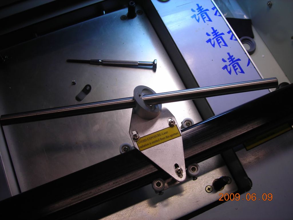
When tightening the little angled mirror mount thing on the head, it is a good idea to remove the mirror and pass a length of 10mm bar through the head. That way, when the bar is parallel to the X axis, we can be sure the mirror in the head will also be aligned. See below.
 |
The ultimate test is now to replace the head mirror and tape a piece of thermal paper to the underside where the lens would normally be. At the two extremes of the head travel (back-left and front-right), fire the laser. If the two spots overlap exactly, you win a prize ;-)
You can now mount the lens and it's ready to engrave.
It's hard to describe everything in detail that I did when I aligned it, but hopefully this should give you some idea what's required. I'd like to point out that there are some minor quirks with the lens in the head, but that only becomes significant when trying to use the air assist nozzle, and I've described them on that page.
| ▲ CO2 laser cutter |