
| ▲ CO2 laser cutter |
This hack allows the controller inside the laser cutter to drive any external device (such as a laser diode) by providing a TTL output signal (well, it's not exactly TTL, more like 4.2V or so).
Usual disclaimer - I accept no responsibility for any damage caused to your laser cutter in the process. Before working on the insides, make sure the cutter has been switched off and unplugged for at least 30 minutes.
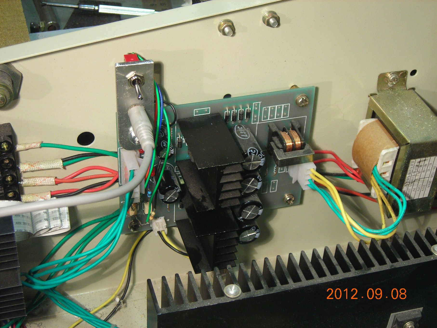
There are three main circuit boards inside the machine. The board on the floor is the power supply for the CO2 laser tube itself. The board mounted vertically on the front, which is connected to the PC's printer port, is the controller - this controls both stepper motors and the laser tube. Lastly, there is a small board mounted on the left-hand wall of the compartment. This contains both a low-voltage (5V and 24V) power supply and an optocoupler to isolate the laser drive signal from the controller board. We will be making modifications to the power supply/optocoupler board.
I've drawn out a diagram of the existing circuit - available both as a "modular" version, showing the connector layouts, and as a "discrete" version, which makes it easier to understand how the circuit works. PDFs here - modular and discrete.
The small PSU board has several connectors of interest. One is a 4-pin connection to the mains transformer. The 6-pin connector provides low-voltage power to the controller board and also carries the laser control signal. There are both 5V and 24V supplies on this connector. The two 5V pins are connected together on the board - the cable only makes connection to the left-hand pin. There are separate grounds for the different supplies - the 24V ground is "GND" and the 5V ground is "VGND", although these are tied together at the controller board end. The pin marked "L" is the laser control signal. The connector I have called J3 (see photos below) goes to the laser power supply PCB and turns the laser on or off.
So, how does it work. Chip U11 on the controller board has an active-low output on pin 17. When this goes low, the LED in optocoupler U12 is turned on. The output transistor of U12 pulls the "L" line low. At the PSU board end, the low L line turns on the LED in optocoupler OK1. This turns on the output transistor of OK1, which in turn switches on the laser power supply. This is easier to understand if you look at the discrete version of the circuit diagram.
The modification is relatively simple. The controller board is left exactly as it is. The PSU board is modified so that a switch can be used to control whether the L line drives either the existing optocoupler on the board (and hence the laser power supply) or an additional optocoupler, which provides a TTL output. Here is the modified circuit.
The additional components are bodged on to the existing board - the optocoupler is glued upside down and the switch and output jack are attached to one of the mounting screws. The particular connections for ground, 5V power etc aren't critical - use whatever locations are most convenient. For example, I took the 5V line and the L signal from the unpopulated connector J2.
The cathodes of the LEDs in both optocouplers are tied together. The switch is used to connect either of the LED anode resistors to the 5V supply line. The output transistor of the new optocoupler (OK2) is used in an emitter-follower configuration to provide an active-high output signal. Note that I could have connected the optocouplers so both were turned on at the same time (i.e. no switch). However, the required current for both LEDs would exceed the output transistor rating of U12, that's why I chose the switched option.
Note that the ground was taken from the 5V ground, since the 24V supply is used for the steoper motors and its ground may be noisier. Admittedly, both grounds are connected at the controller board, so I'm not sure how much of a difference this makes.
Here are some photos of the circuit boards both before and after modification. There are various notes on them - part names correspond to those in the PDFs linked above.
 Power supply board |
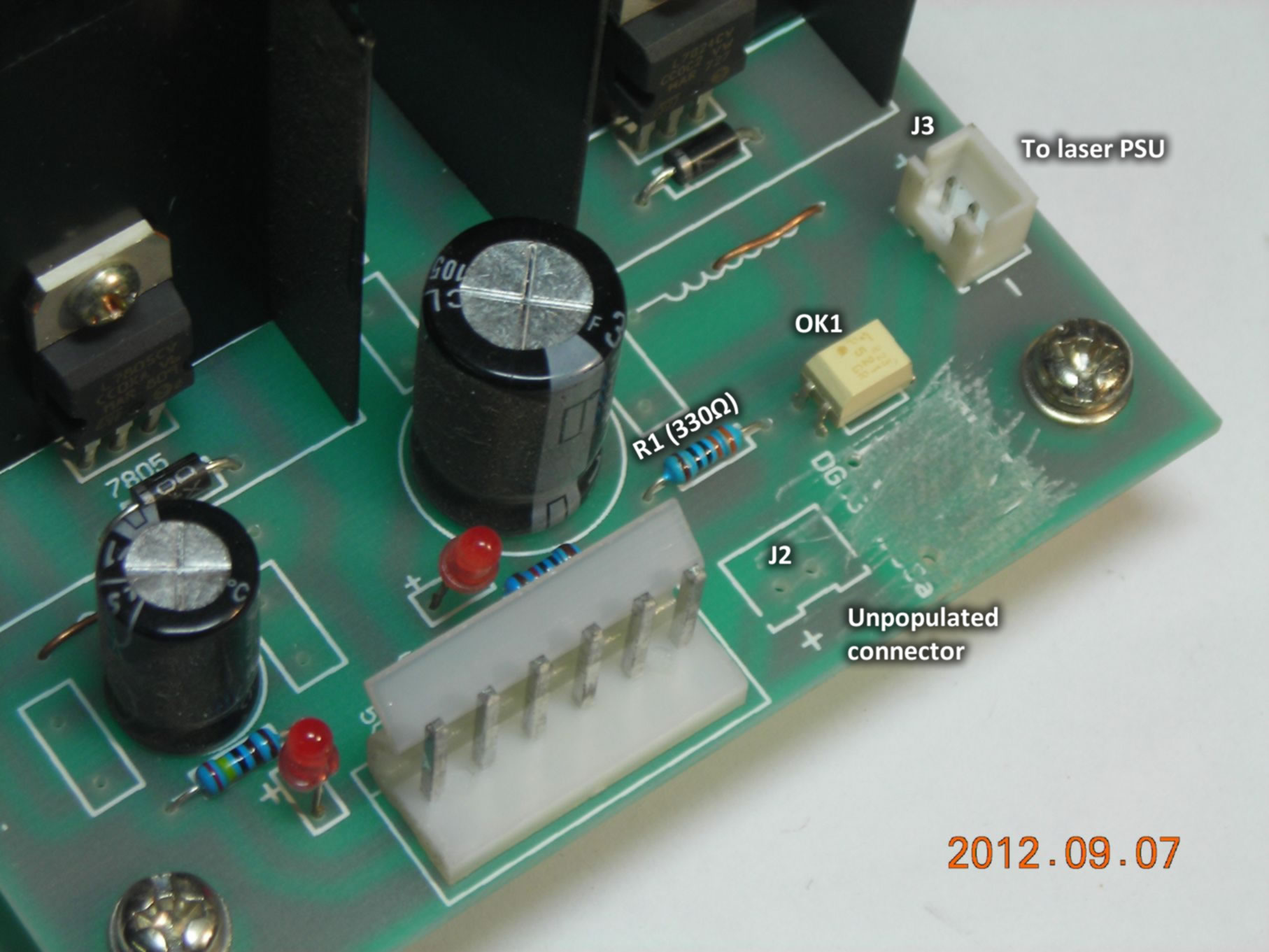 Existing connectors and components |
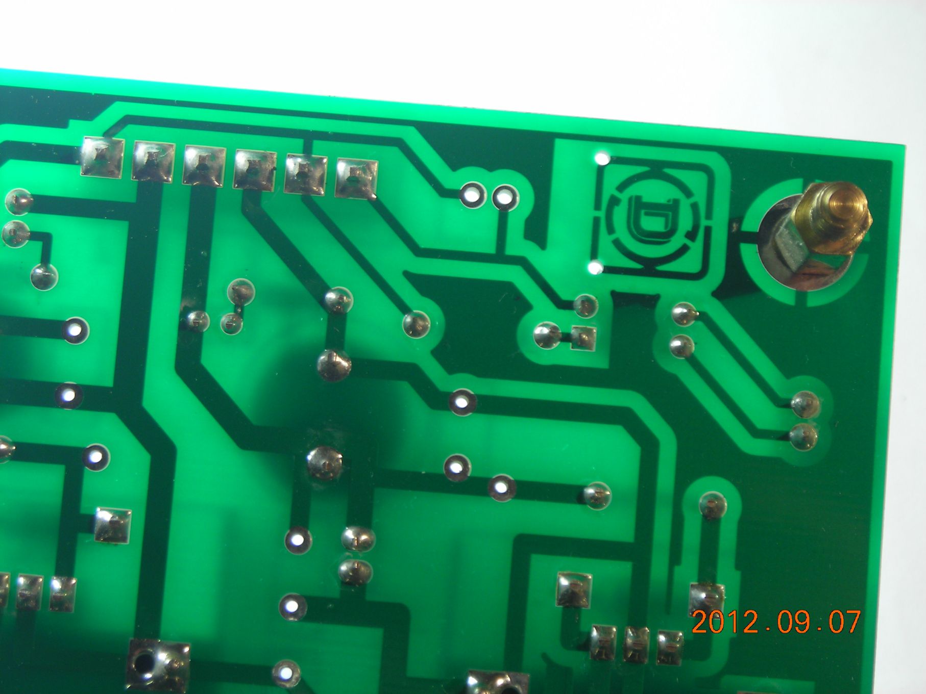 Underside of PSU board |
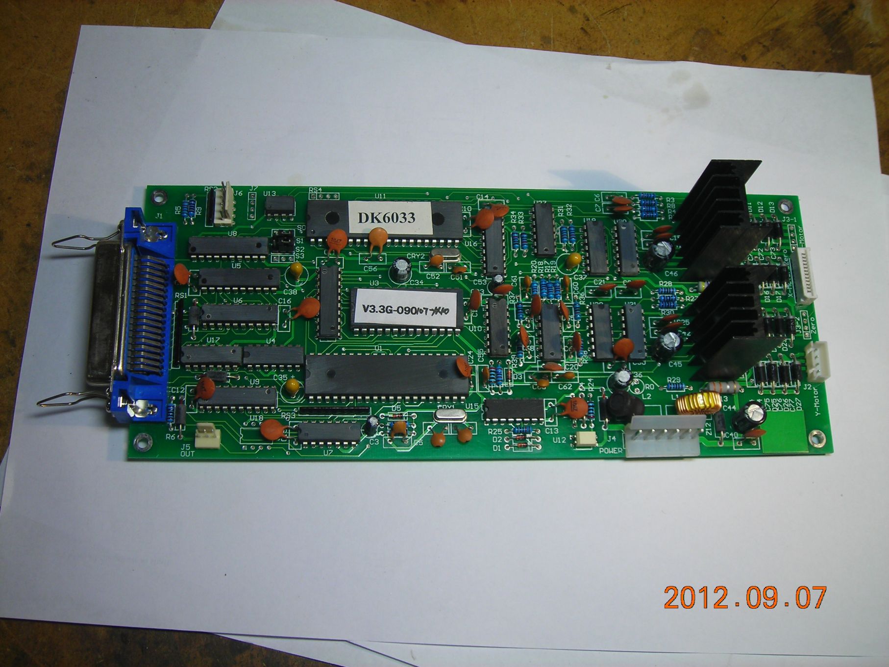 Controller board |
 Controller board connector |
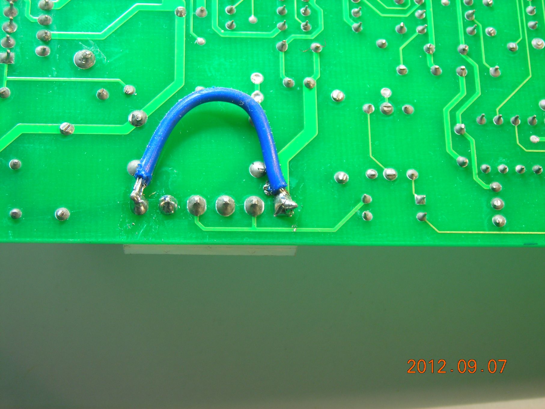 Underside of controller board connector. Blue wire is connecting both the 5V and 24V grounds. |
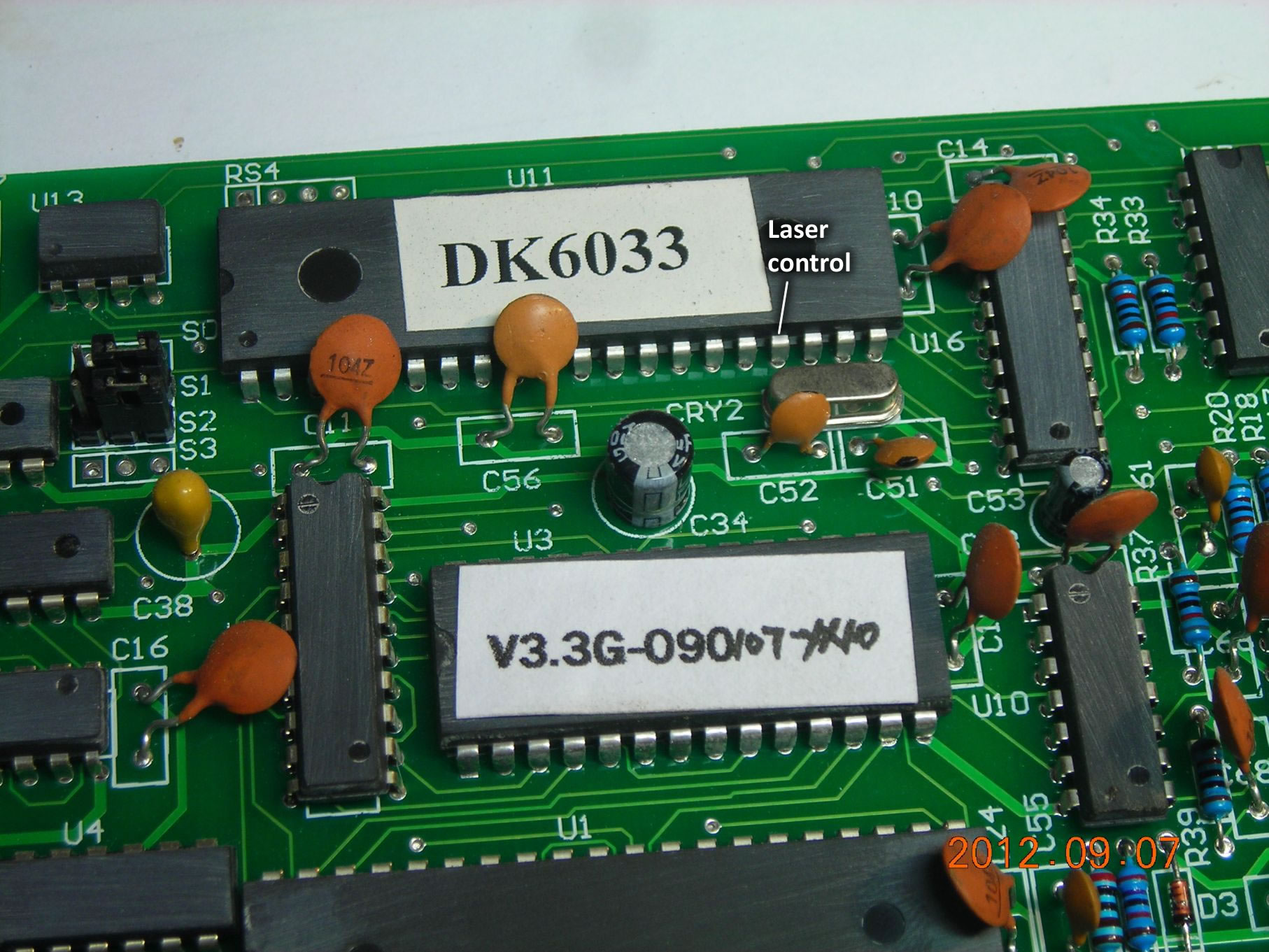 Upper chip (U11) controls the laser |
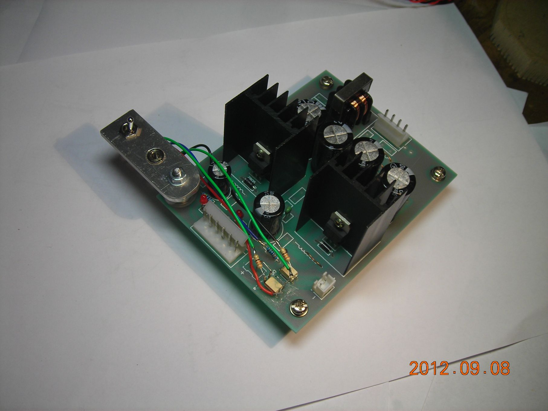 Modified PSU board |
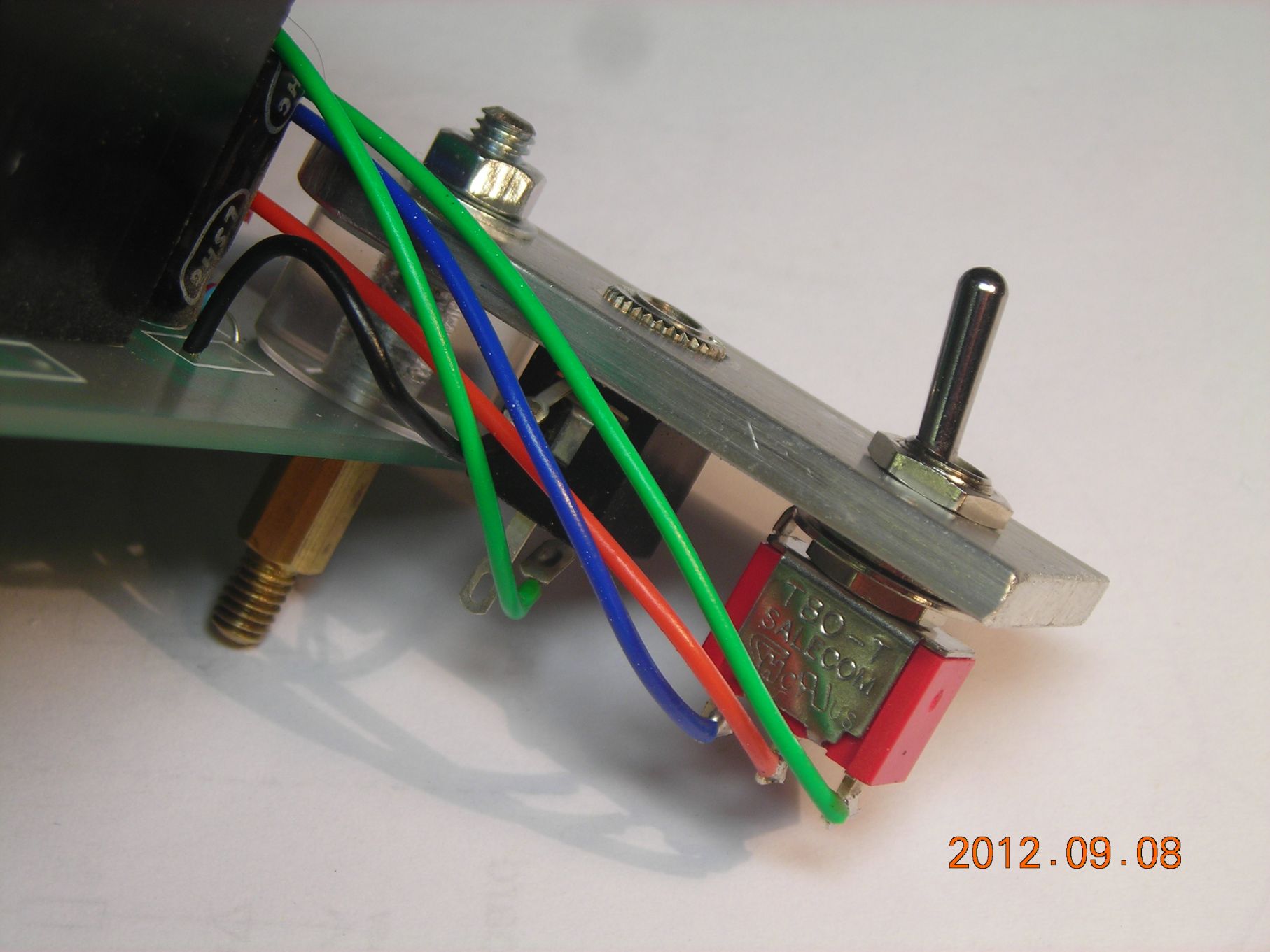
 Control switch and output jack on left |
 |
 |
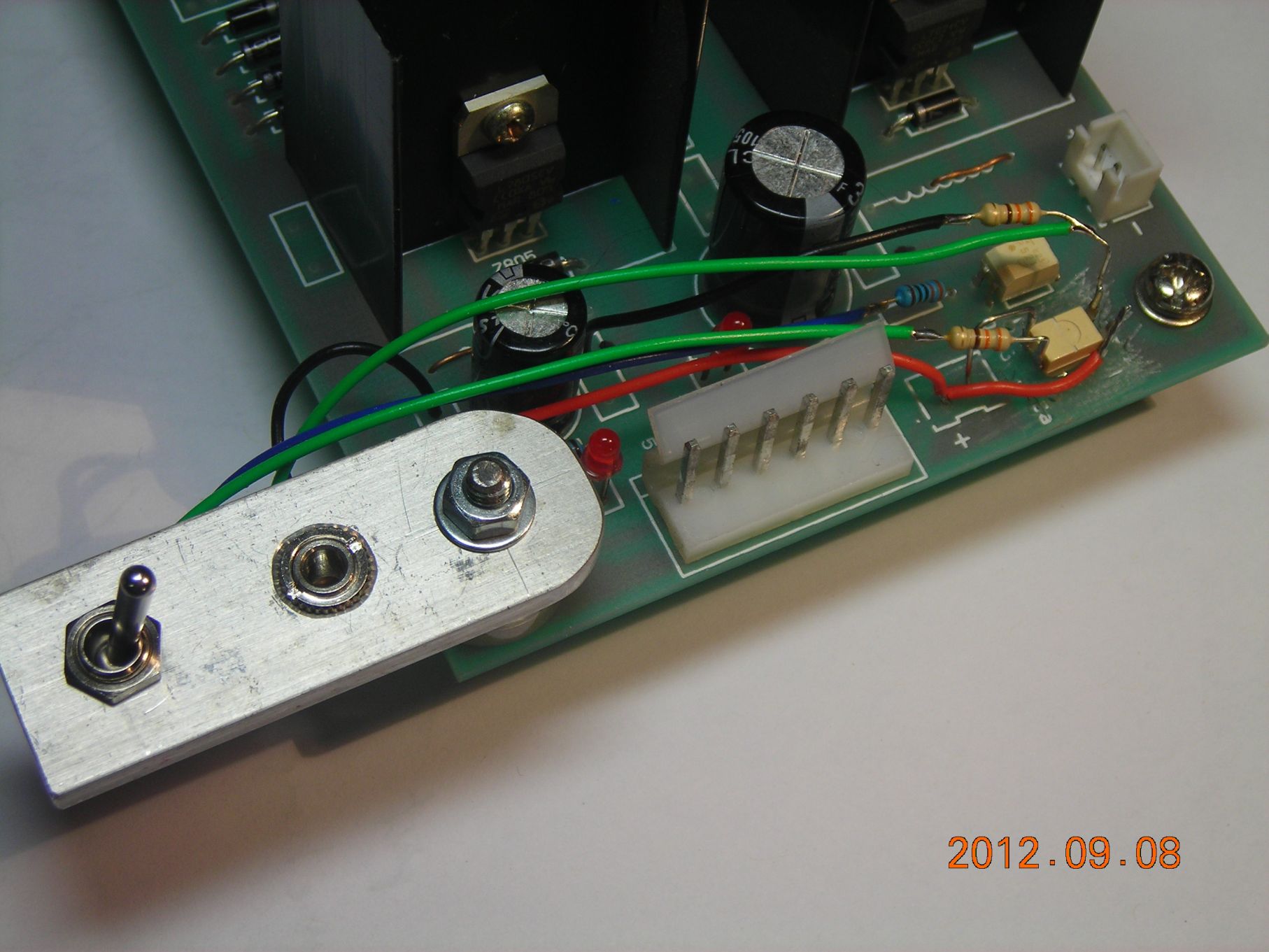
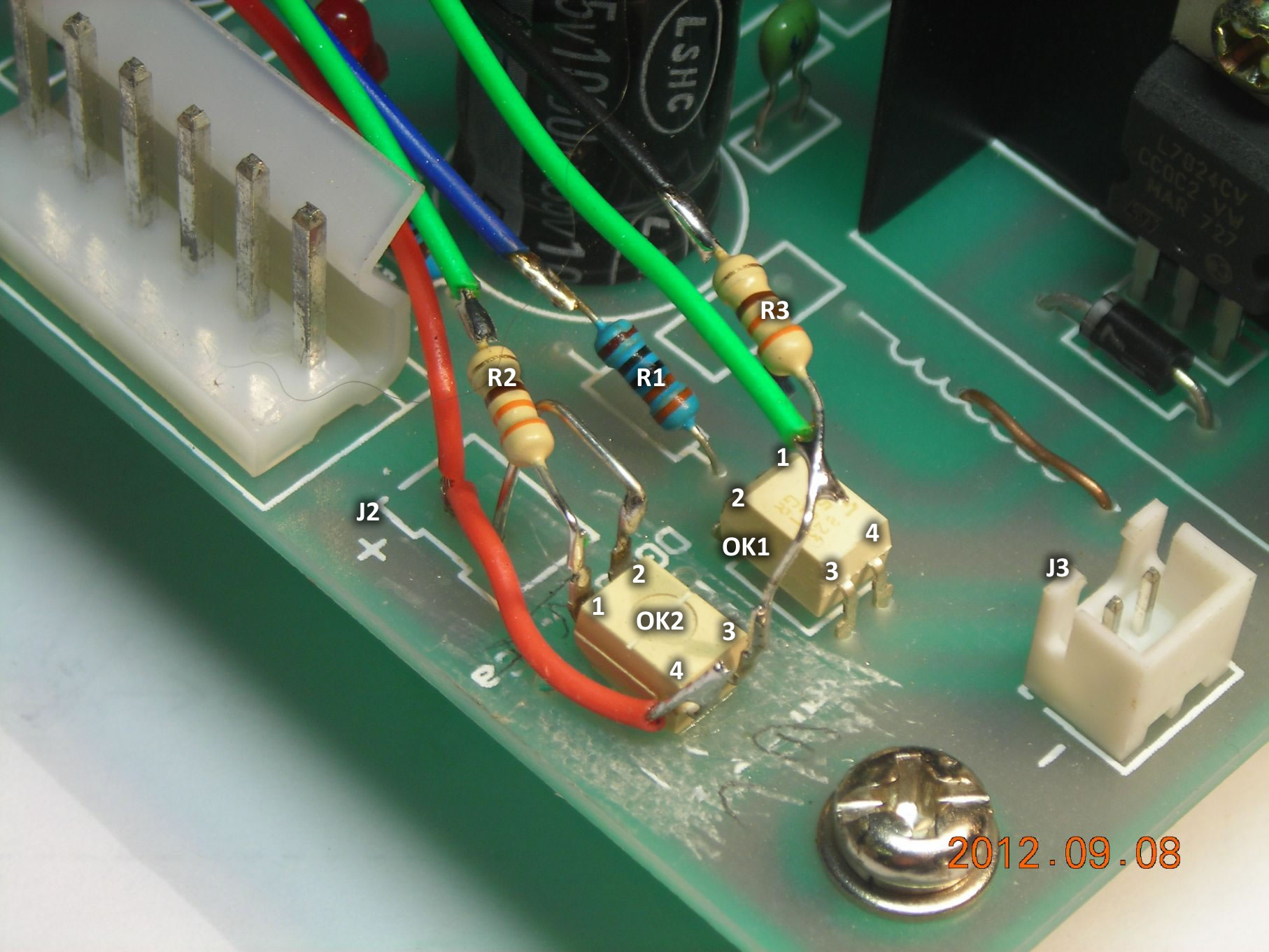 New components - refer to circuit diagram. Part names correspond. |
 |
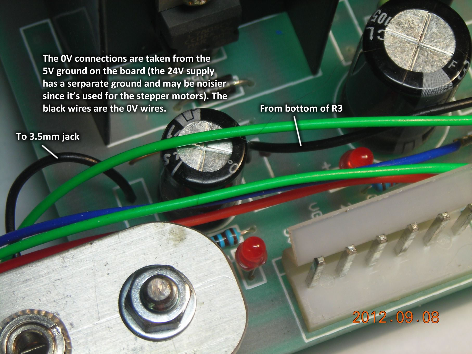 Ground connections |
 New board mounted inside laser |
 |
 Output cable connected |
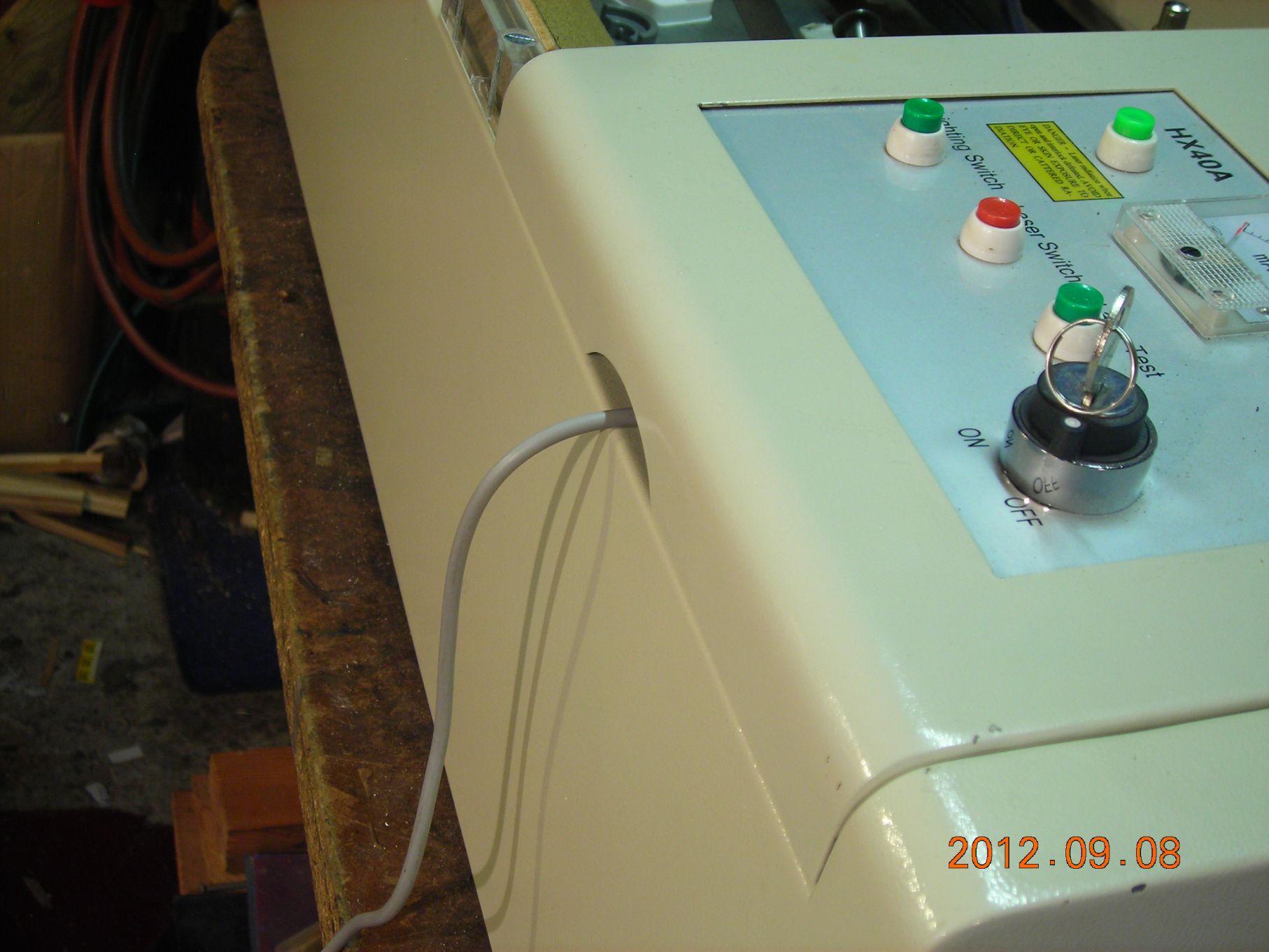 Cable fits nicely under the lid |
Here are some graphs showing the waveforms of both the microcontroller output and the final TTL output, both at switch on and off, and with the output both unloaded and loaded with a little laser pointer module (the TTL output is connected to the control input of the laser pointer).
As expected, there is a bit of a delay between the microcontroller and the final output - the TLP521 optocoupler isn't particularly fast, with switching times on the order of 5-10µs. The worst delay observed is during switch-off with a loaded output - the delay is around 25µs. However, even at a 10cm/s scanning speed, this corresponds to a distance of only 2.5µm, which is negligible.
 Switch on |
 Switch off |
| ▲ CO2 laser cutter |