| ▲ Workshop |
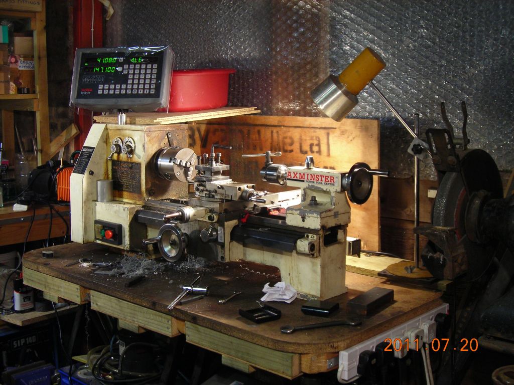
I eventually decided to buy and fit a digital readout to my lathe (an Axminster BV20M). It makes life so much easier and saves having to rely on a 1"-travel dial indicator, which was my only means of accurately positioning the carriage.
The display console and scales were bought from Allendale Electronics (http://www.machine-dro.co.uk). The original manufacturer is Guangzhou Lokshun CNC Equipment Ltd. (http://en.sino-ld.com/dro/cn/) - DRO products are branded "Sino".
Console is the SDS6-2V. Allendale Electronics: http://www.machine-dro.co.uk/sds6-2v-universal-display-console-2-axis-display.html. Sino: http://en.sino-ld.com/dro/cn/product/index-2.jsp?catid=81|96&id=173.
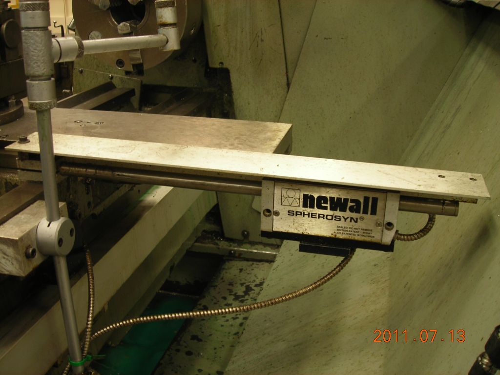
Long (carriage) axis is a GS300 scale, 470mm travel. Allendale: http://www.machine-dro.co.uk/gs300-470-standard-glass-scale-470mm-reading-length.html. Sino KA-300:http://en.sino-ld.com/dro/cn/product/index-2.jsp?catid=81|97&id=179. The cable exit direction from the reading head was reversed to make snaking the cable around the lathe easier.
Short (cross slide) axis is a GS500 scale, 120mm long. Allendale: http://www.machine-dro.co.uk/gs500-120-slim-glass-scale-120mm-reading-length.html. Sino KA-500: http://en.sino-ld.com/dro/cn/product/index-2.jsp?catid=81|97&id=180.
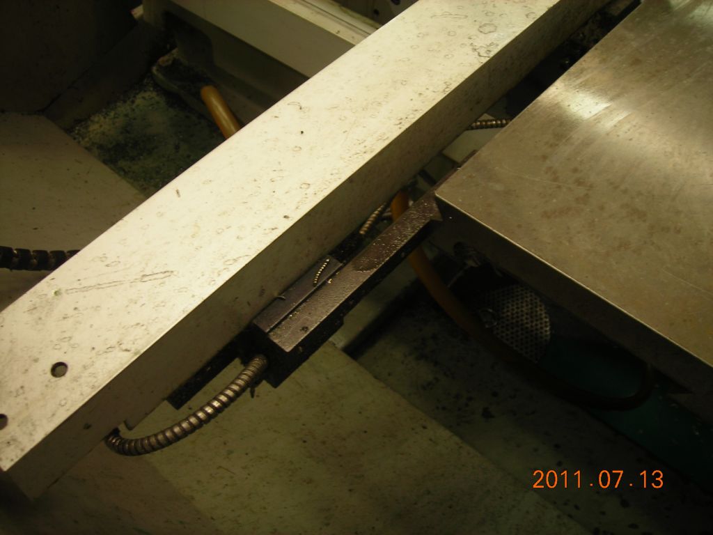
I grossly underestimated the amount of work required to fit the scales. No fault of the scales themselves - everything has to be accurately aligned, and this required many different brackets and mounting plates to be designed and made. The scales do come with a selection of brackets, but I ended up only using one (the long "L") and making the rest from scratch. It took about a week of solid work to get it working happily. I'm not going to go into a lot of detail - every lathe is different, and the photos are just to give some idea how I proceeded with mine. The pictures are chronological, but often some bits are dissassembled out of order. The captions may not mean a lot, but I was stuck for something to say in a small space.
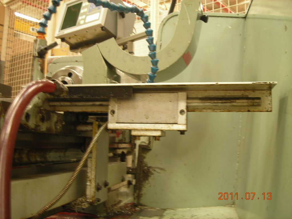
 Lathe before |
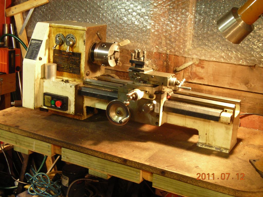 Lathe before |
 Lathe at university |
 Lathe at university |
 Lathe at university |
 Lathe at university |
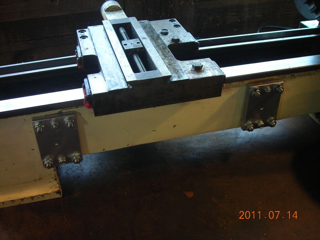
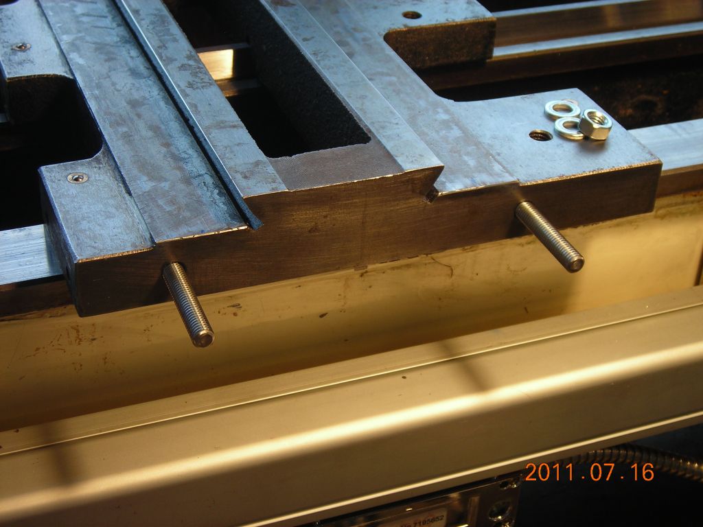
 Mounting screws for levelling plates |
 Mounting screws for levelling plates |
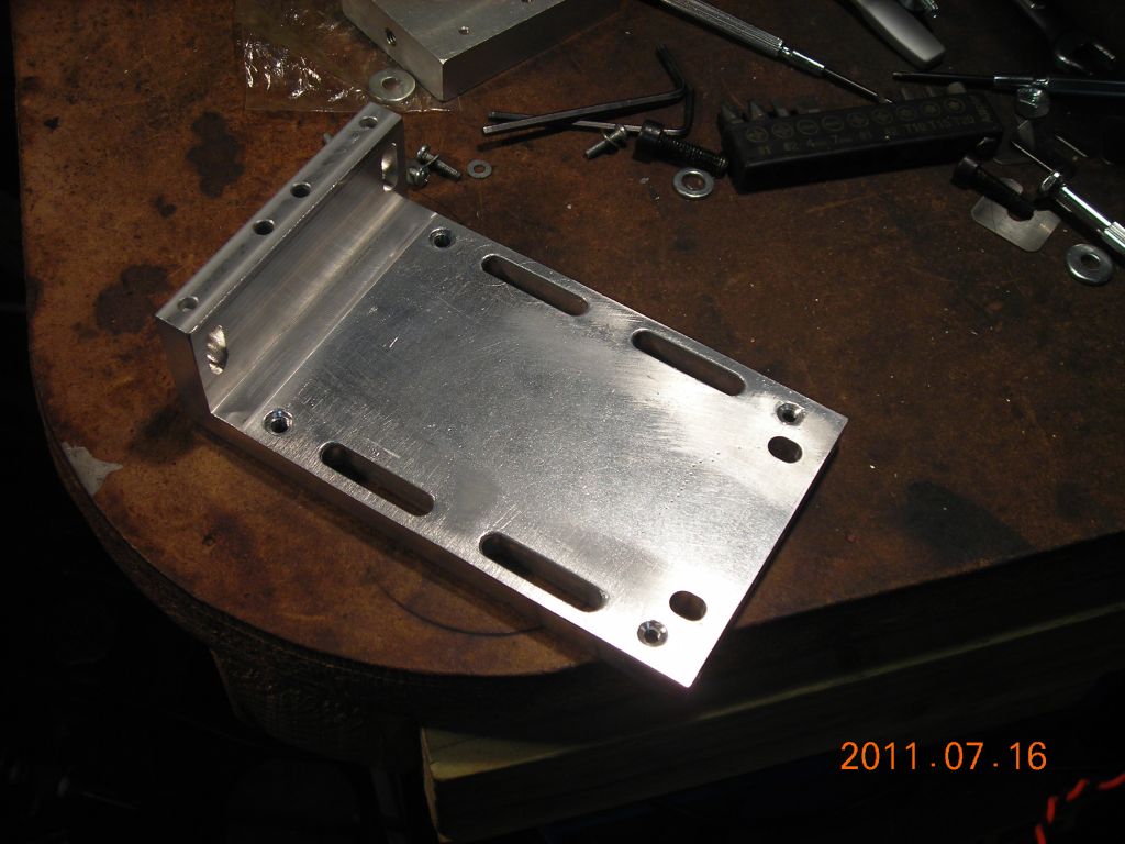
 Levelling plate |
 Levelling plate |
 Levelling plate in position |
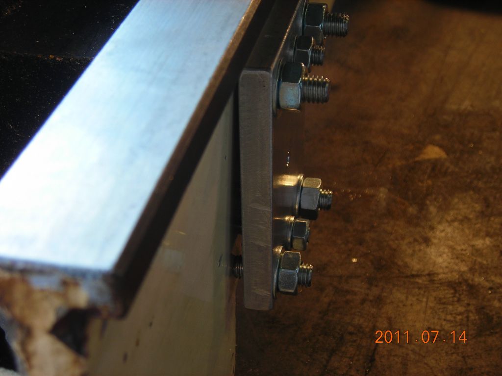 Levelling plate - side view |
 Both levelling plates |
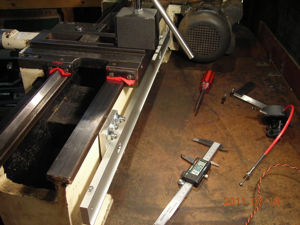
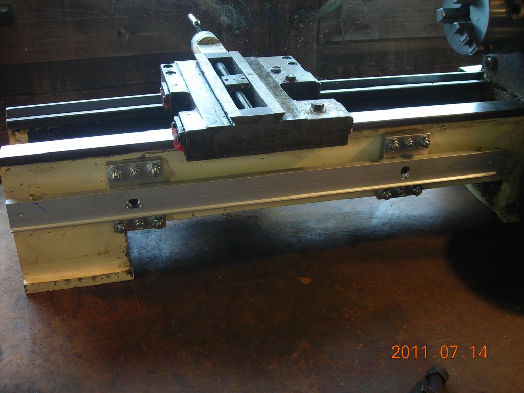 Scale mounting bar attached |
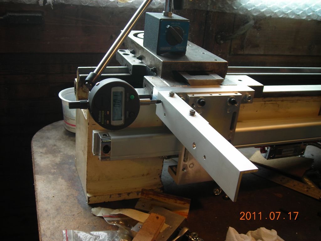
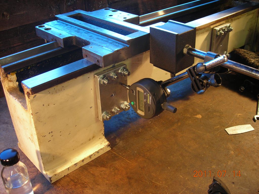 Clocking the levelling plates |
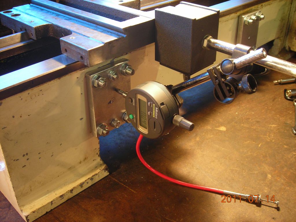 Clocking the levelling plates |
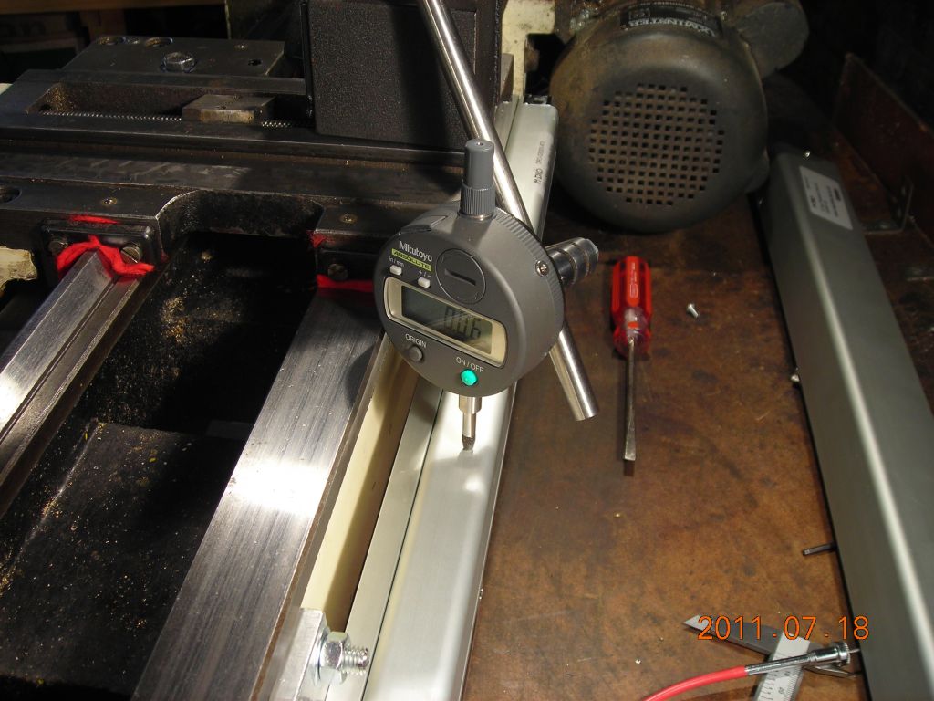
 Clocking the top of the scale |
 Clocking the top of the scale |
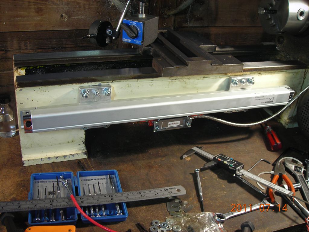 Scale mounted |
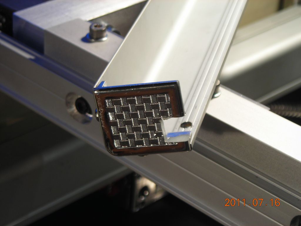
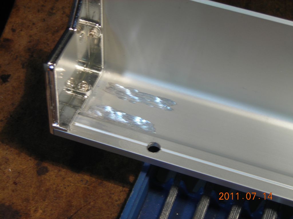 Clearance areas ground inside the cover..... |
 .....to clear these two little high bits |
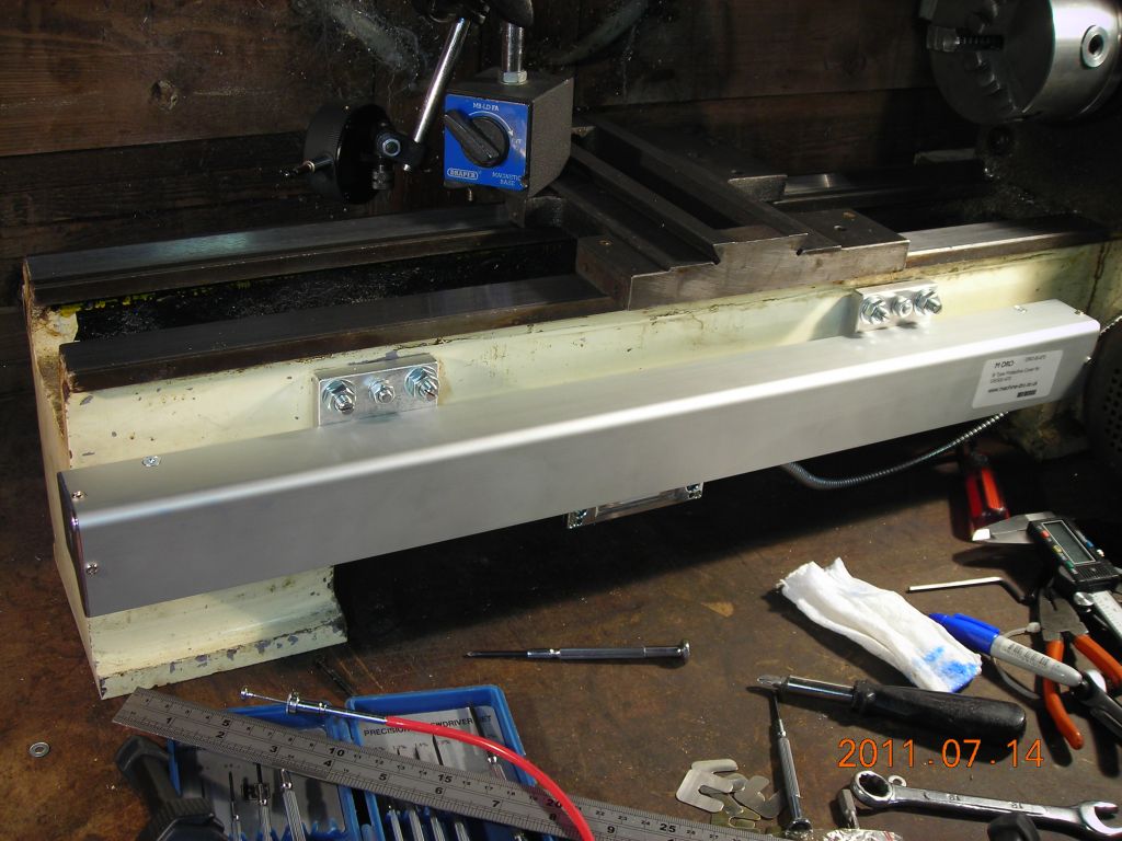 Cover in place |
 Holes for spacer block on carriage |
 Bolts in place |
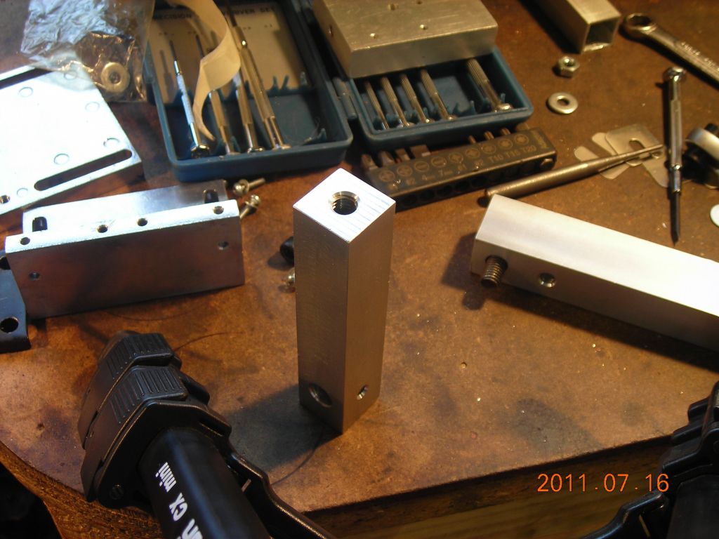
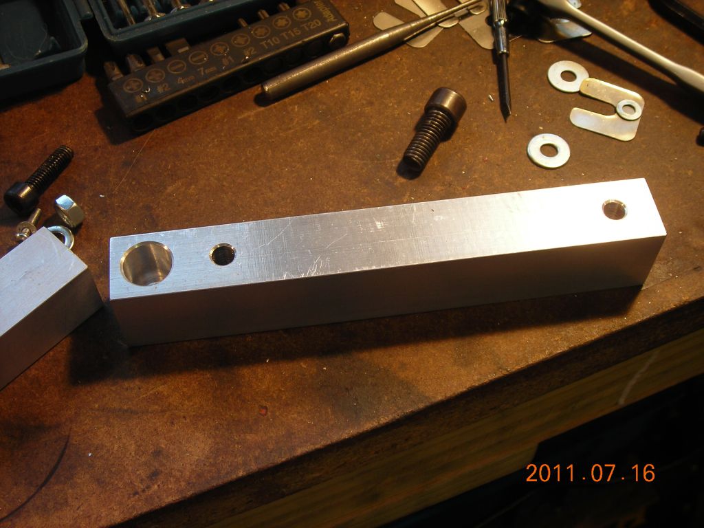 Spacer block |
 Cross slide scale mounting bar |
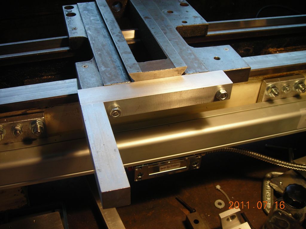 Spacer block and mounting bar attached to carriage |
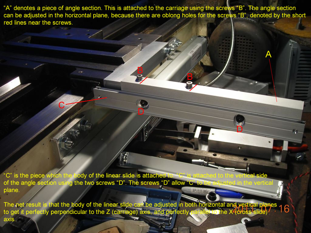
 Angle section for mounting cross slide scale |
 Scale mounting rail |
 Cut to clear one of the wiper screws |
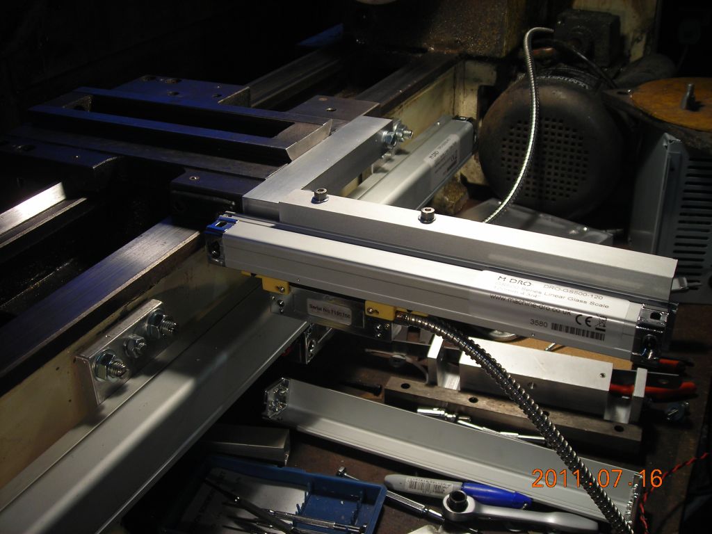 Scale in place |
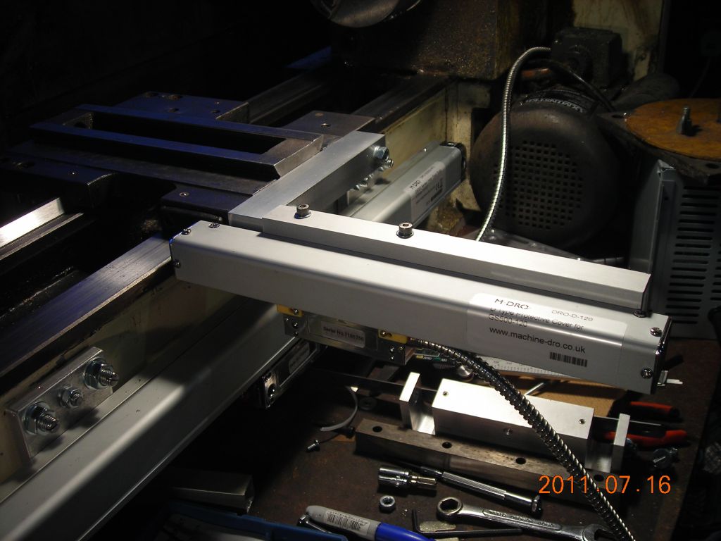 Cover in place |
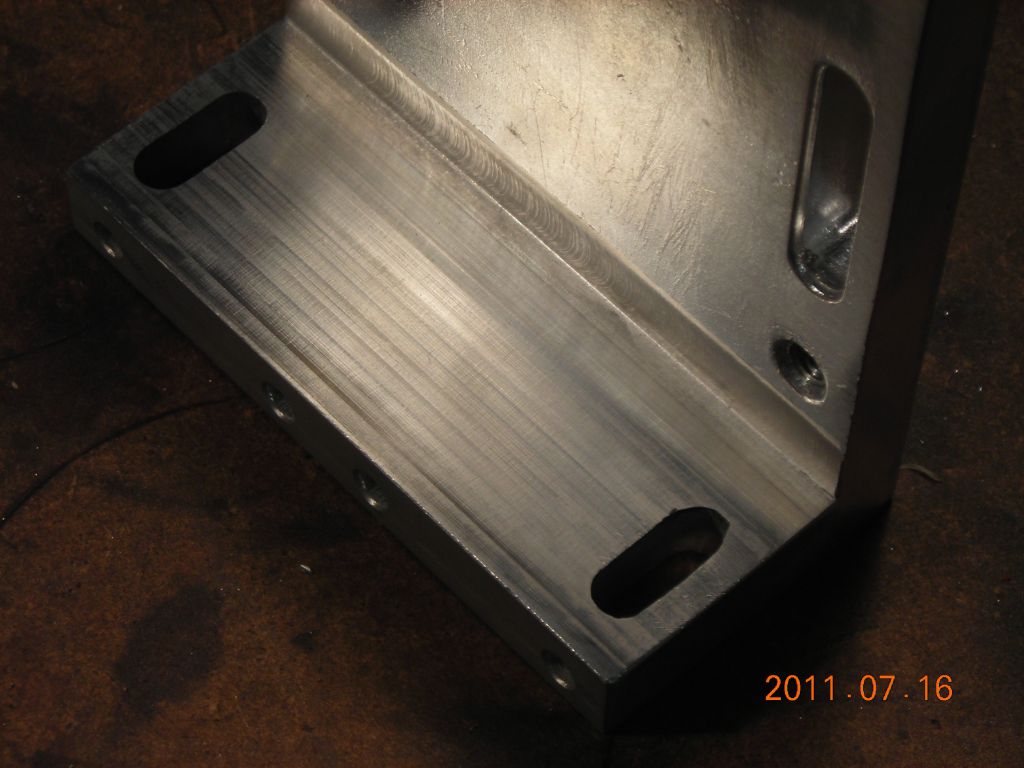 Cleaned up inside of big bracket |
 Big bracket (supplied) |
 Big bracket in place |
 Clocking the cross slide scale mounting angle |
 Clocking the scale mounting bar |
 End plugs for 20mm Al box section |
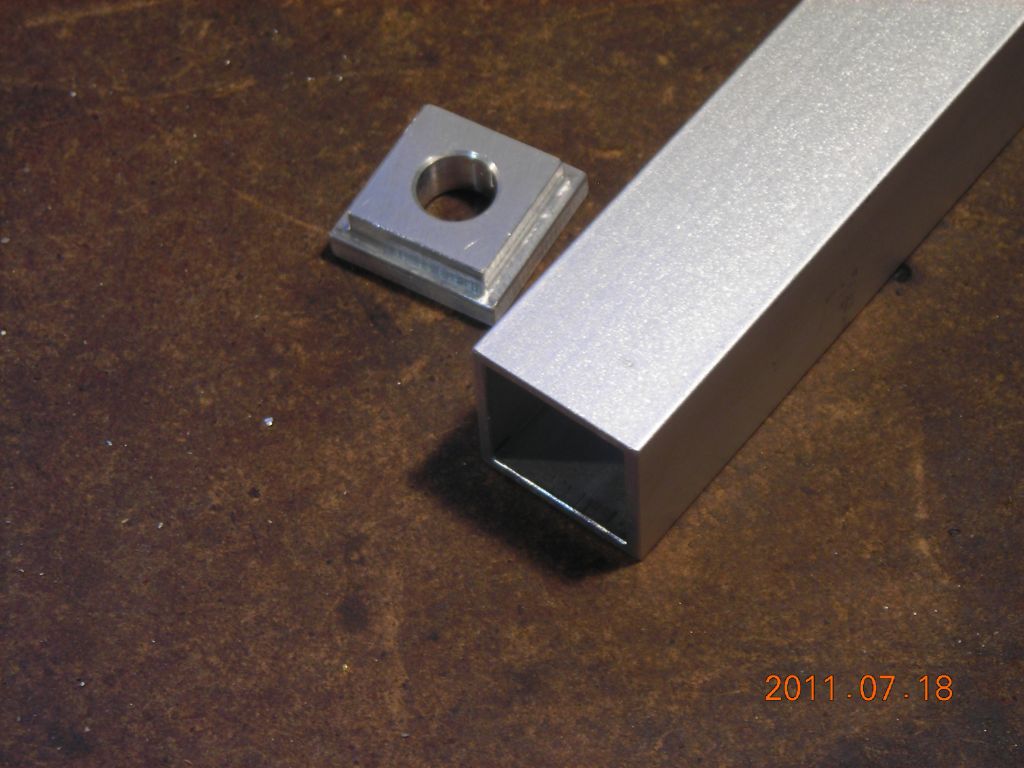 One end |
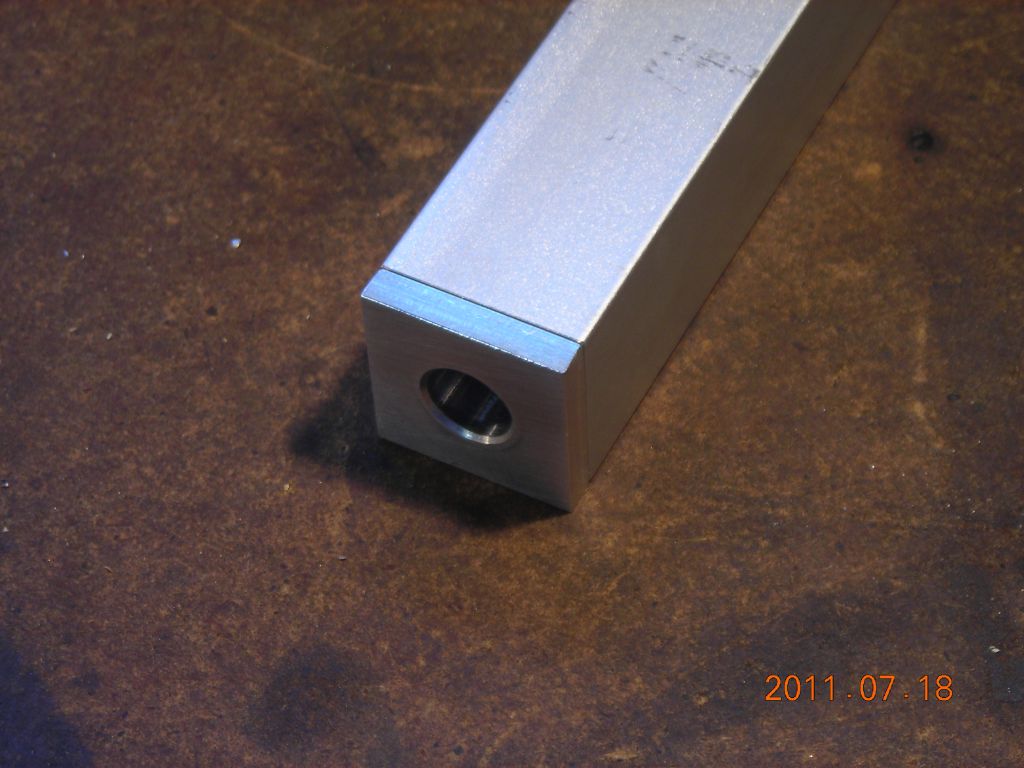 Inserted |
 Hole in cross slide for reading head mounting bar |
 M8 threaded rod in hole |
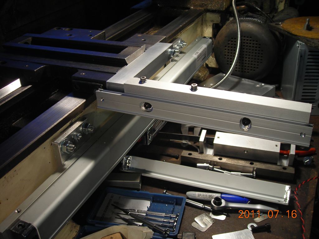
 20mm box section mounted |
 Small bracket on reading head |
 Bit of disassembly here - back to the two levelling plates |
 Clocking the levelling plates |
 Mounting rail attached |
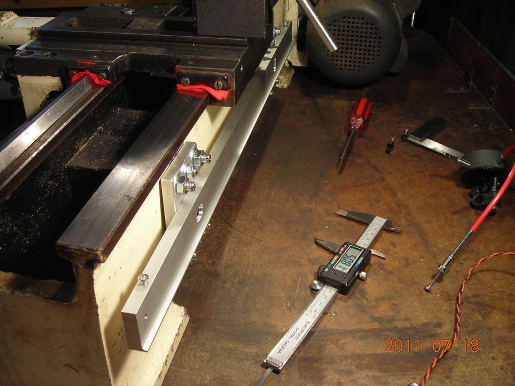 Mounting rail attached |
 Clocking top of scale |
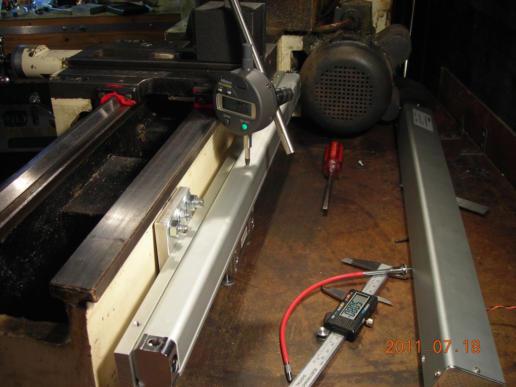 Clocking top of scale |
 Big bracket attached |
 Reading head attached to big bracket |
 Clocking cross slide scale mounting bracket |
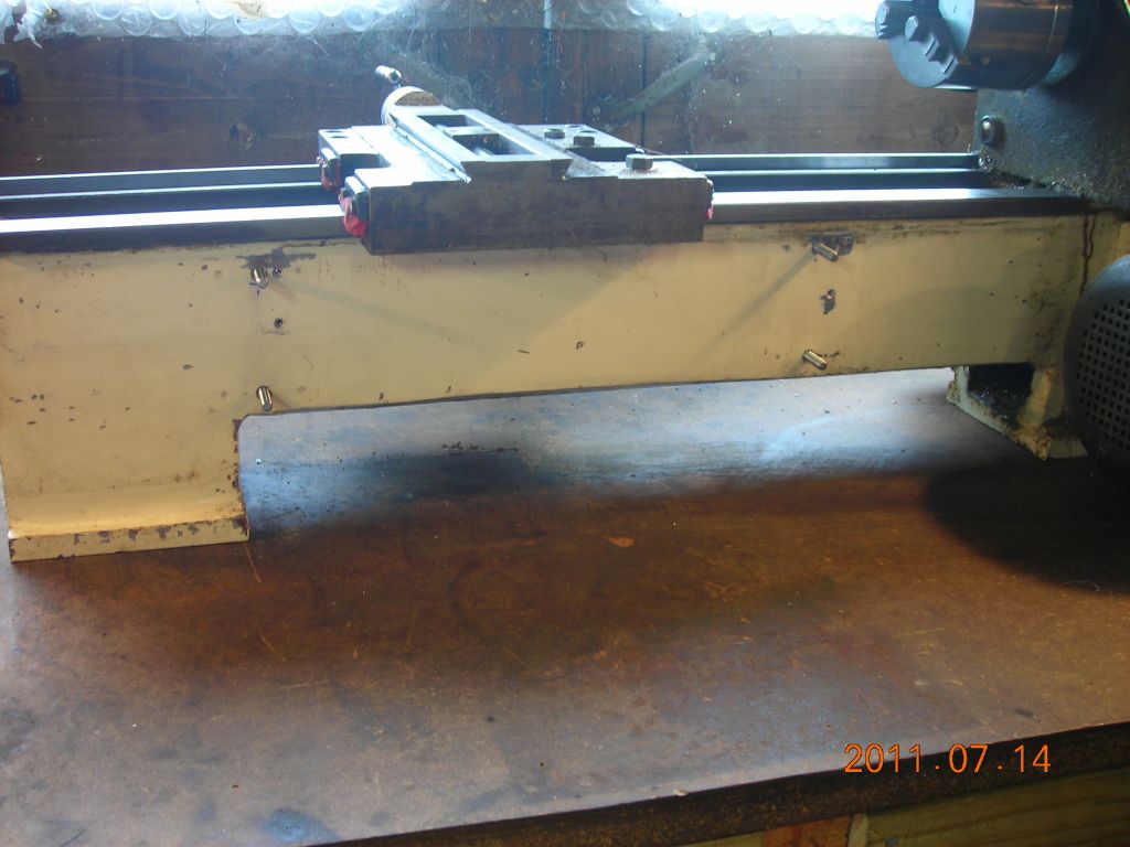
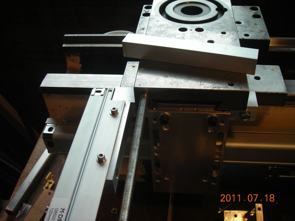
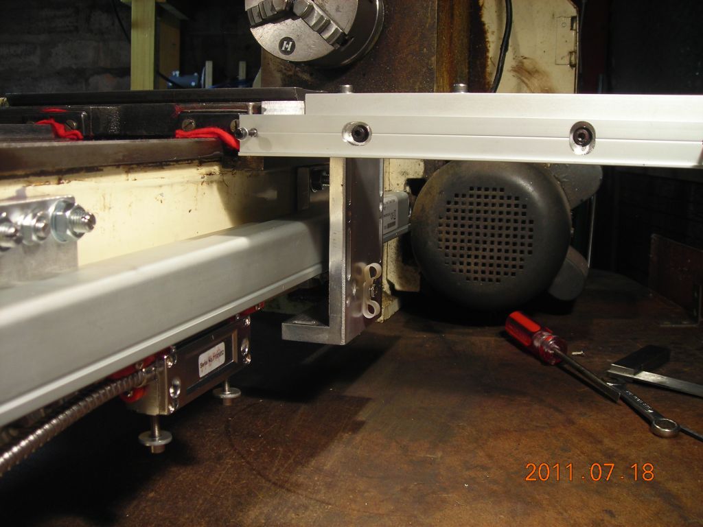
 Rear view of both slides |
 Closeup |
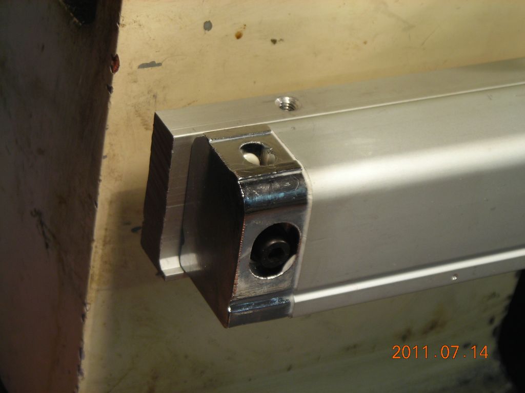
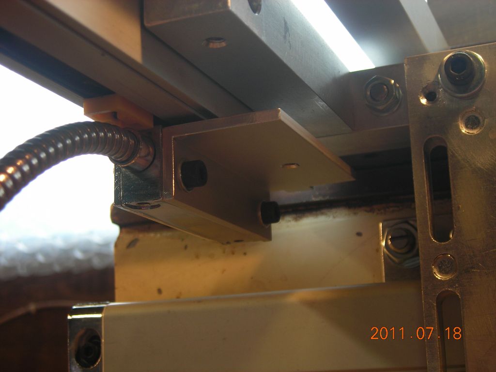
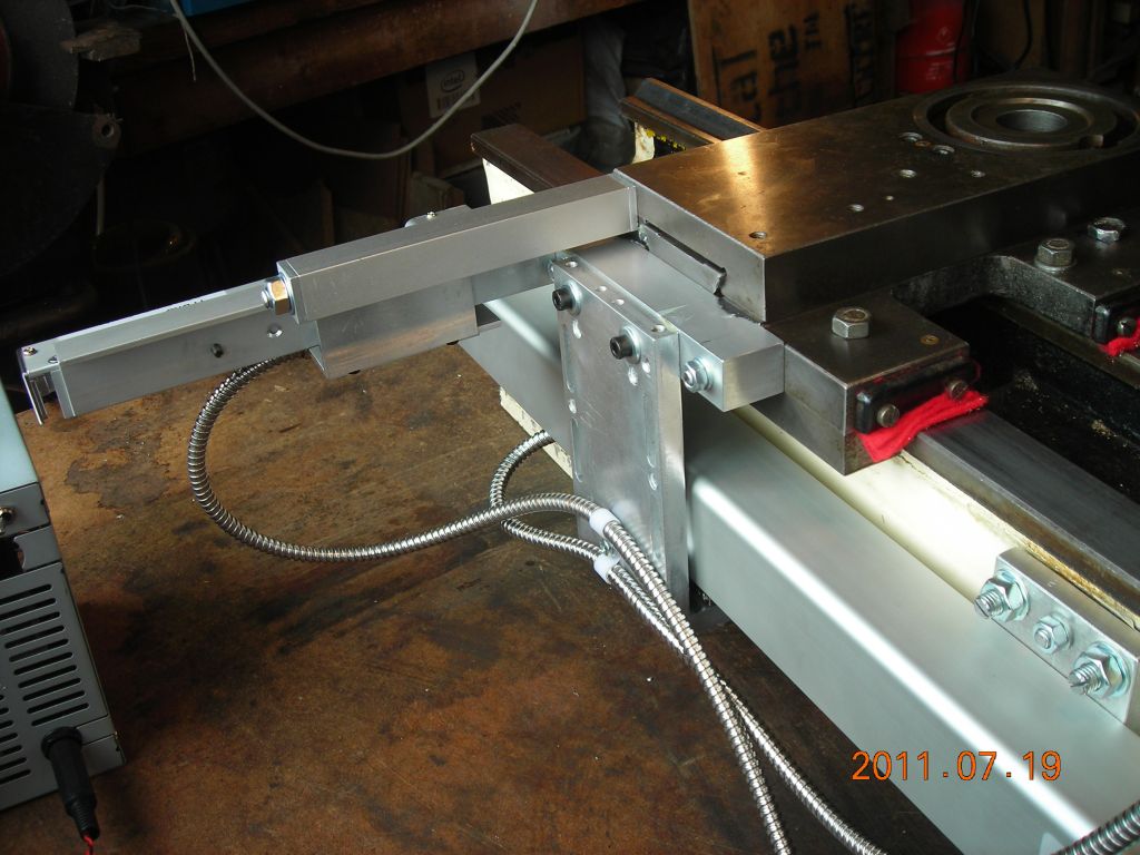
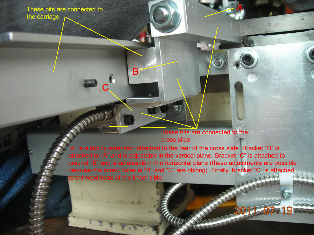
 End view showing the complicated brackets to connect the cross slide to the reading head |
 Another view of the brackets from hell |
 The display is bolted on to the headstock gearbox cover |
 The completed lathe! |
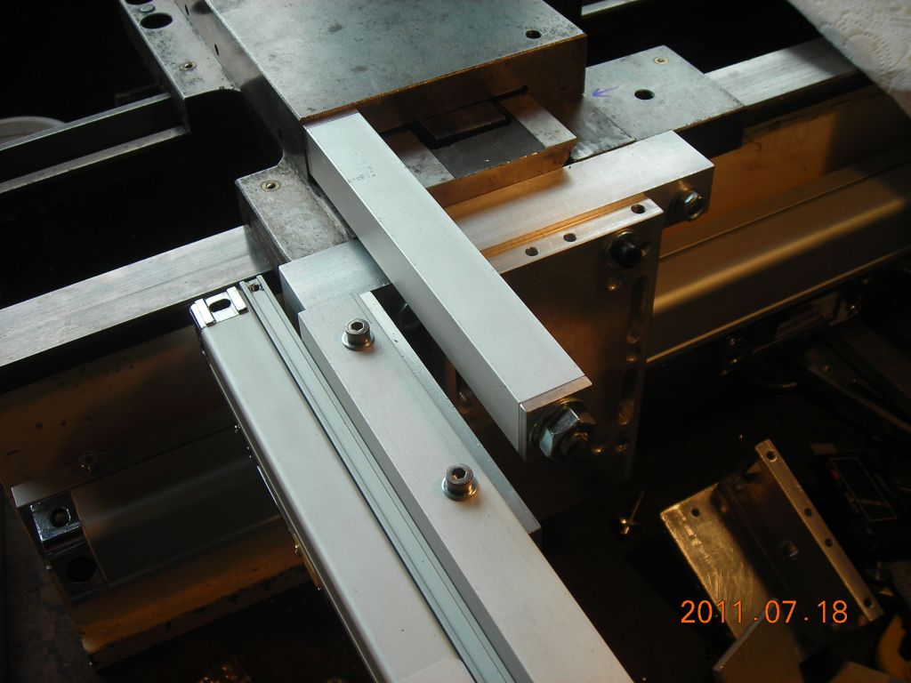
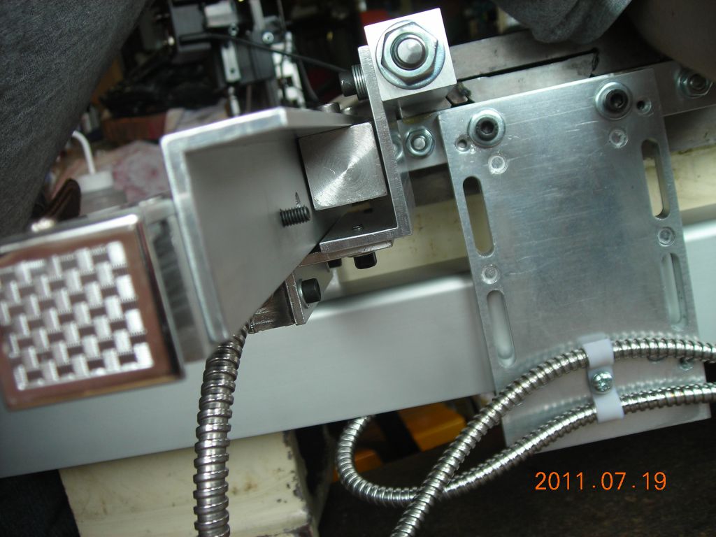
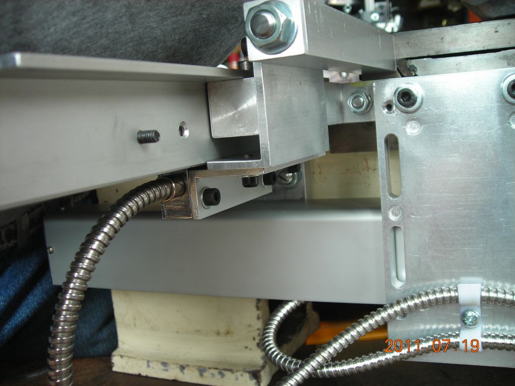
31/08/11: I've added some notes to the two pictures below to try and explain the cross slide attachment a bit more clearly.
 |
 |
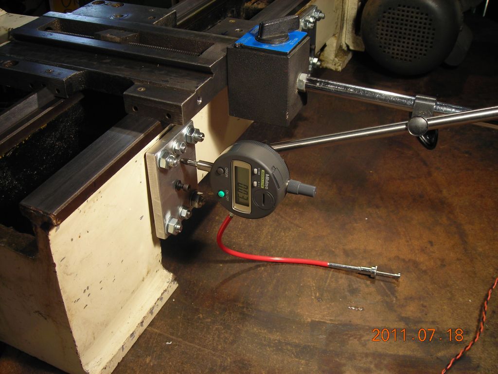
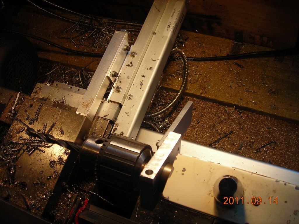
14/09/11: One day, I needed to measure the travel of the tailstock accurately, and I was thinking about possibly mounting a digital caliper on the tailstock. However, I did some searching on the web, and found this idea somewhere - I can't remember where, but my thanks to whoever thought on it originally! It's very simple - a split collar with a flat sticky-out bit is clamped to the tailstock ram (I had made one previously) and is adjusted so it rests on any part of the carriage. As the tailstock is moved in, the sticky-out bit pushes the carriage along and this movement can be read using the carriage axis DRO. Very simple!
 Split collar clamped to tailstock ram |
 Sticky-out bit touching the carriage |
| ▲ Workshop |