| ▲ Workshop |
I needed some heavy-wall tubing with an accurate 6mm internal diameter (ideas for small hydraulic/pneumatic cylinders, amongst other things). EBay provided me with some nice cold-drawn seamless stainless tubing which was nominally 6mm ID by 10mm OD. I got it from Diamond-E-Supplies (EBay shop or website). Unfortunately, the tubing was actually around 5.9mm ID and 10.1mm OD, which is no good since I needed it to fit 6mm drill rod/silver steel as a piston.
I discovered that I could force a 6mm ball bearing through a short length of tubing using the hydraulic press, which enlarged it to just under the required diameter (the tubing contracts slightly after the ball bearing passes through). However, this was impractical on longer lengths. The required force was around 200-300kg, which is within the range of a manual hand winch, so I decided to rig up a drawbench for doing longer lengths. After some experimentation, I found it was relatively easy to enlarge the tubing using a swaging tool pulled through it, with sizes going up in 0.05mm increments.
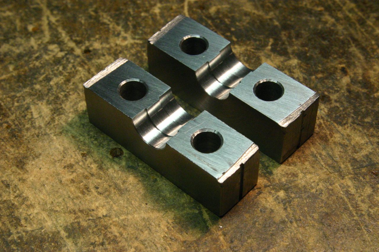
First requirement was a good clamp for the end of the tubing. I was initially just going to make a simple split clamp and hope that friction would be enough, but (fortunately, as it turned out) I decided to add a ridge inside the clamp to locate in a turned groove in the tubing, just to ensure that it couldn't pull through. The clamp was made from two pieces of ½" square mild steel bar.
I cut two pieces of the steel bar about 40mm long, clamped them together with a 0.5mm aluminium shim in the middle, and TIG-welded the ends together to hold them. I placed some aluminium spacers on the sides, because the chuck jaws didn't close far enough. Once all the machining is done, the welds will be cut apart. I also ran some Loctite into the seam just to ensure everything was well stuck together.
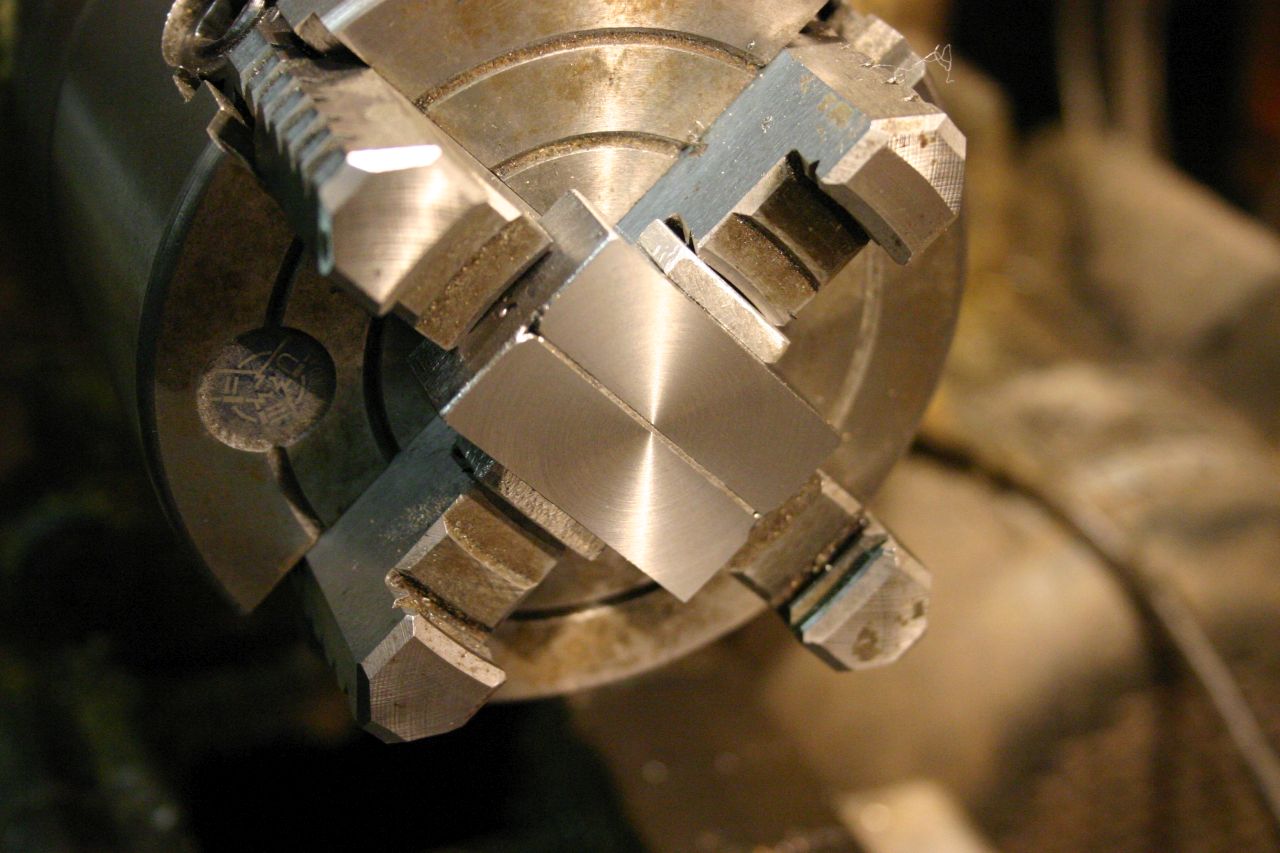
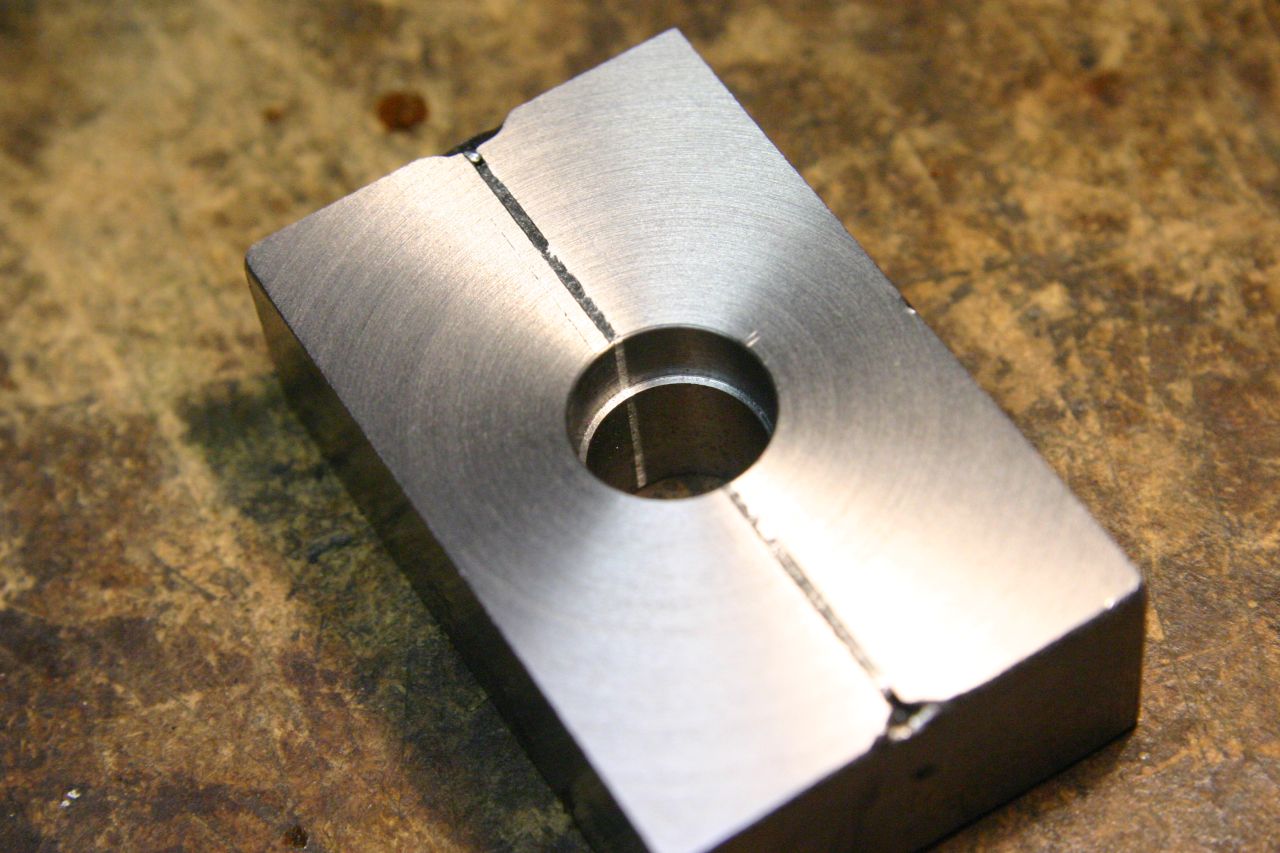
The combined block was then centered in the 4-jaw chuck, faced and bored. The block is then flipped, re-centered and the counterbore on the other side machined. Bolt holes were drilled for M6 bolts, then the blocks were cut apart and cleaned up.
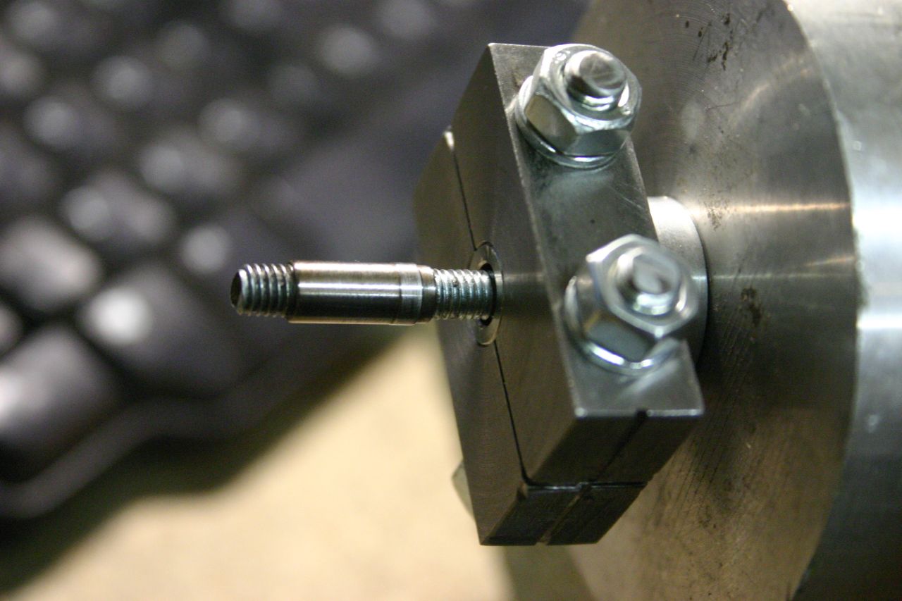
One end of the tubing was turned down to 9.9mm (the tubing expands slightly during swaging, and this ends up being around 10mm, a good fit for the clamp) and a groove turned for the ridge inside the clamp.
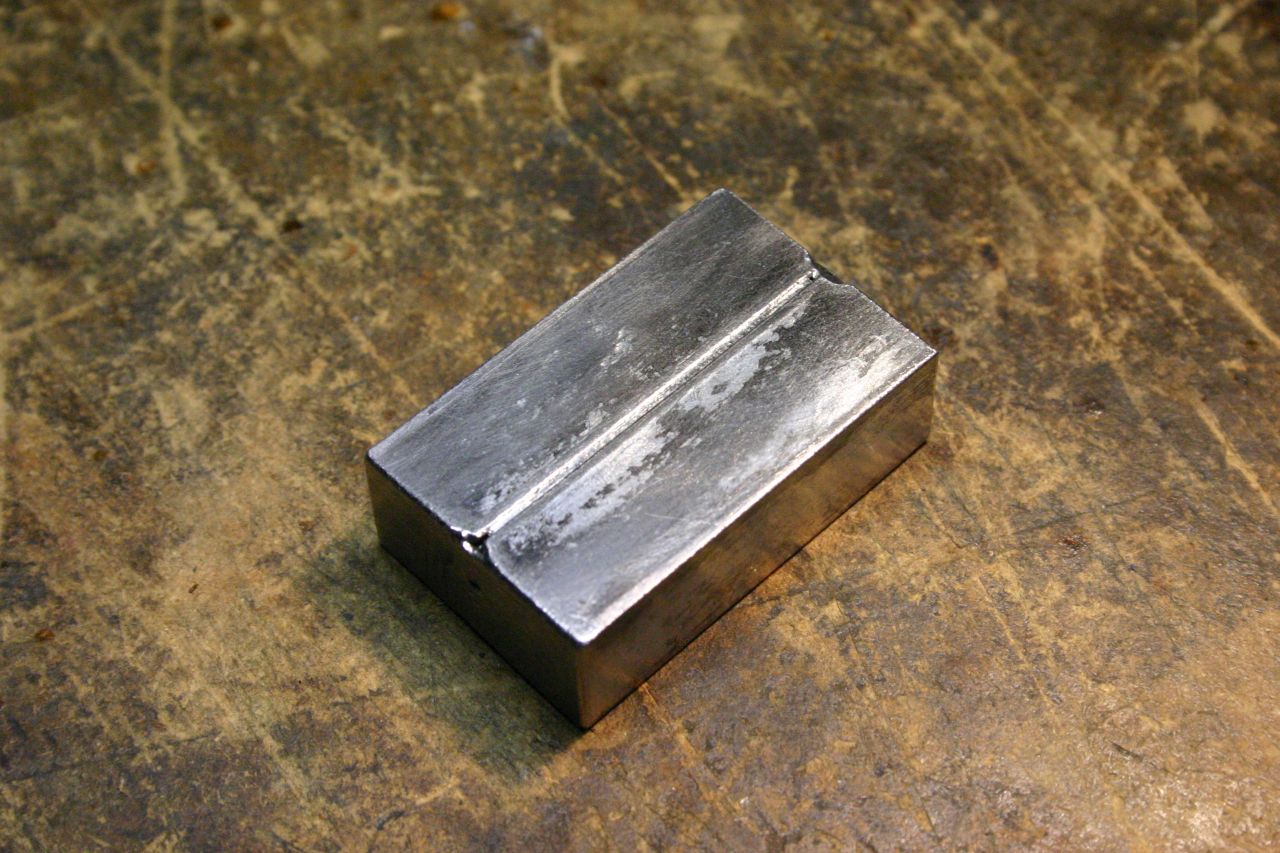 Blocks welded together |
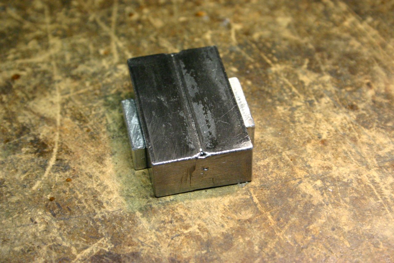 Spacers added |
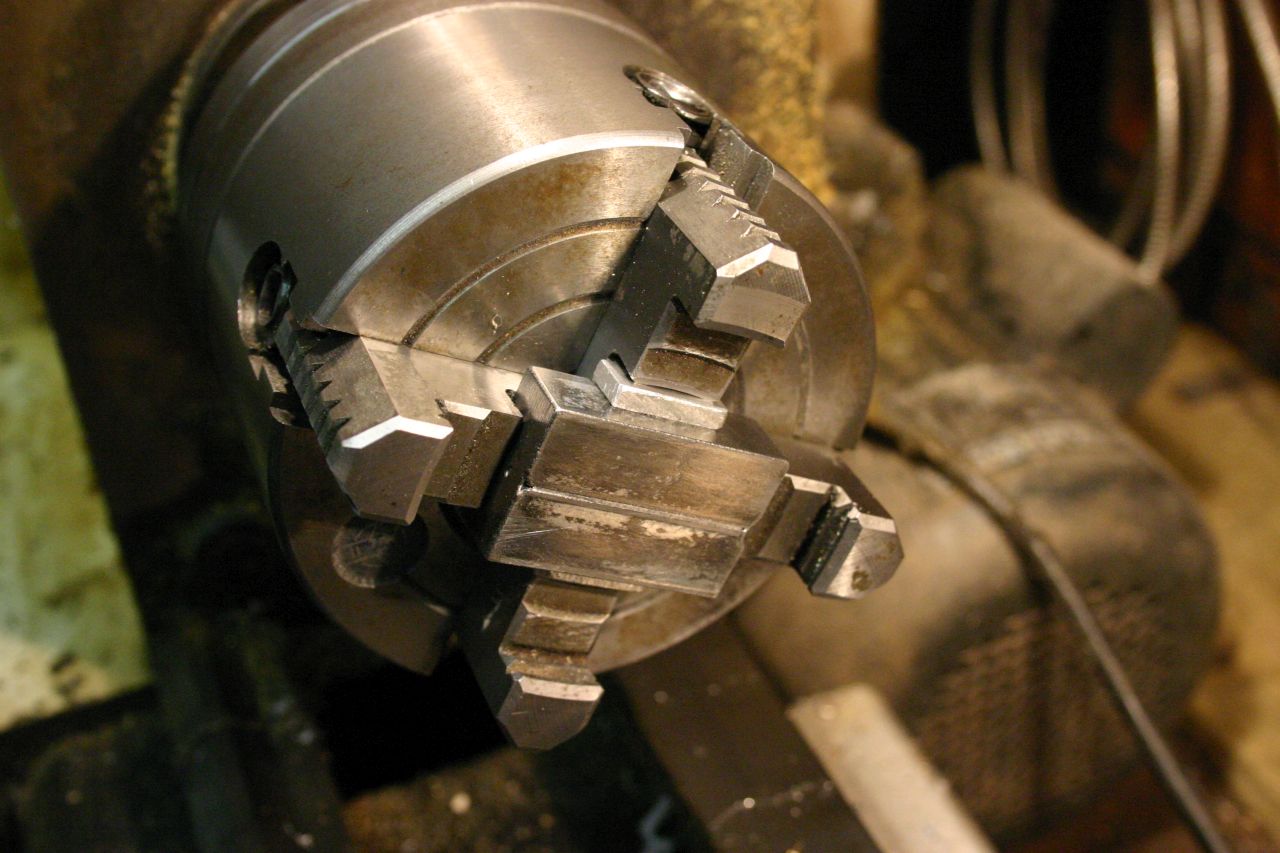 Centered in chuck |
 Faced |
 Bored |
 Closeup showing counterbore |
 Re-centering the other side |
 Bolt holes drilled |
 |
 Blocks apart |
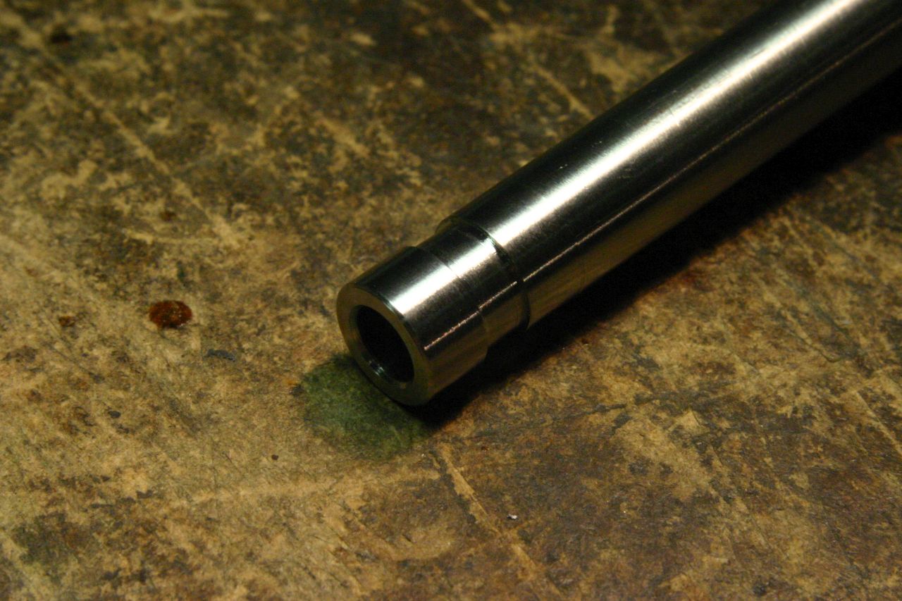 Tube end machining |
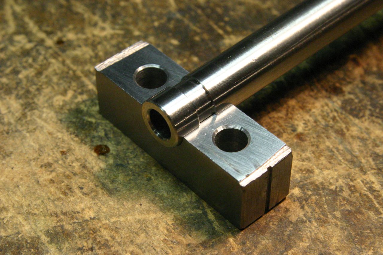 Fis neatly into the block |
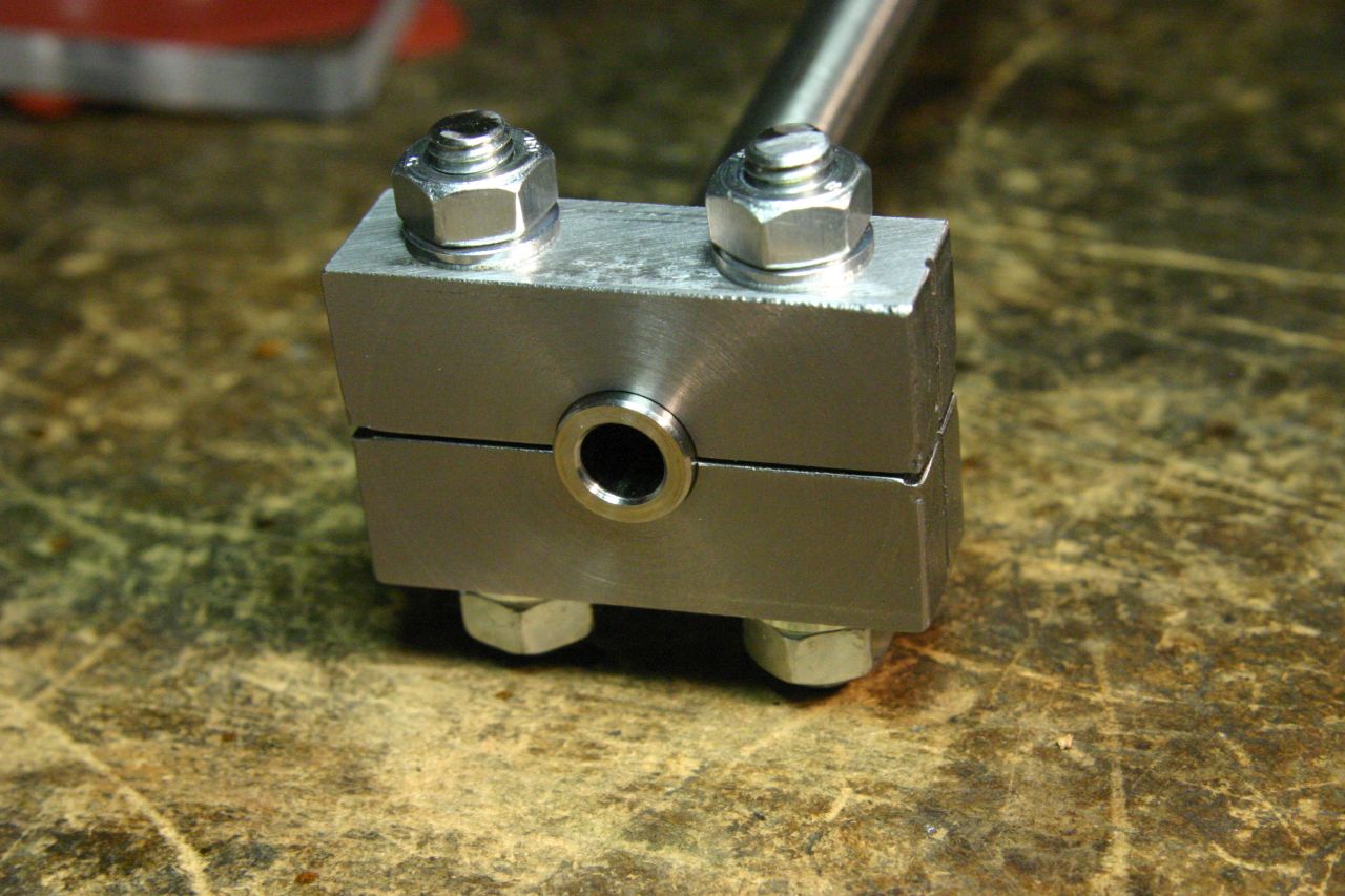 Other block fitted and bolted together |
Safety note, and materials: The drawbench setup is a little rickety. Although I was fairly confident in my calculations and choice of materials, there's always the chance of something being overloaded or snapping. Wear some form of eye/body protection and don't get too close to the drawbar or winch!
Both the drawbar and U-bolt shown in the photos below are made from 8.8 grade high-tensile steel, NOT cheap hardware-store steel. The drawbar is M5 threaded rod, and I calculated that it should be able to withstand nearly 1000kg before breaking.
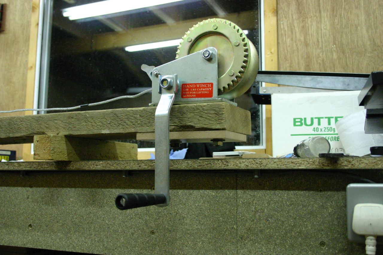
I got a cheap hand winch off EBay, rated to 1200lbs (540kg). This came with loads of cable (10m, I think) on the spool - the first time I tried it, all the cable got bunched up and knotted in the spool, making it very difficult to remove. Since I only needed about 80cm of travel, I removed most of the cable and left just enough to give the required travel.
I made an assembly from some bent M8 threaded rod (8.8 high-tensile, again) and some 3/8" steel plate to connect the drawbar to the winch's shackle.
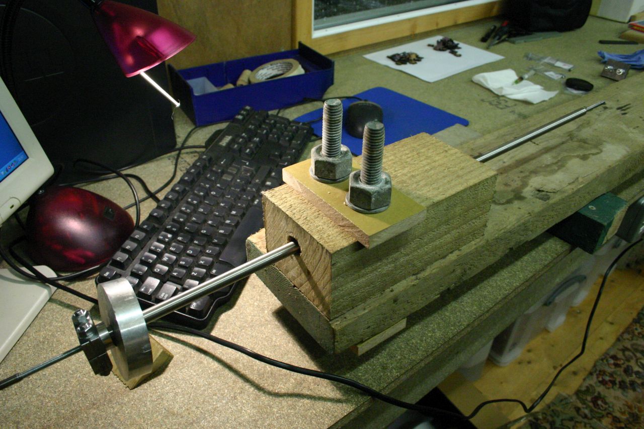
The base is a scaffolding board, approximately 6x2". The winch is attached to one end with 3x M10 bolts and a piece of MDF flooring underneath to act as a bit of packing to spread the load from the nuts.
The tubing is restrained at the other end of the base with a piece of 4" fencepost. This has a hole drilled lengthwise and is secured to the base with a couple of 5/8" bolts, again with MDF flooring packing top and bottom. Some aluminium discs are used to spread the load from the tube clamp and prevent it digging into the end of the fencepost.
The drawbar is M5 threaded rod, again 8.8 high-tensile steel. The swaging tools are turned from silver steel/drill rod and are hardened/tempered to straw yellow. They are threaded on to the drawbar. If you look closely, you'll see that the "working" end of the swaging tool is at the front of the direction of travel, with the rest of the tool's diameter being slightly smaller. This ensures that the tool is under compression. If the working end was at the rear of the tool, it would most likely snap from the pulling force.
I found that 0.05mm was the largest size increase which it was possible to pull through the tubing - any more simply required too much force. I ended up with swaging tool sizes of 5.93, 6.00, 6.03, and 6.08mm. I also found that the tubing contracted by about 0.05mm after the tool had passed through so, for example, the 6.08mm tool would leave a 6.03mm bore.
Although some of the swaging tools were very tight (see the video later), the whole process went without incident and I was able to pull all four tools through. I passed each tool through twice, just to make sure the tube was expanded as far as possible. The end result was an internal diameter of around 6.03mm, exactly what I needed.
The outer diameter of the tubing also increased, unsurprisingly. You can see this in the last photo, where the clamp has dug into the tubing as it's tried to expand. The red arrow indicates the edge of the tubing clamp. I cut off this end of the tubing since it was slightly bent after drawing.
 Overall view of the drawbench |
 Tube clamp and restraint block |
 |
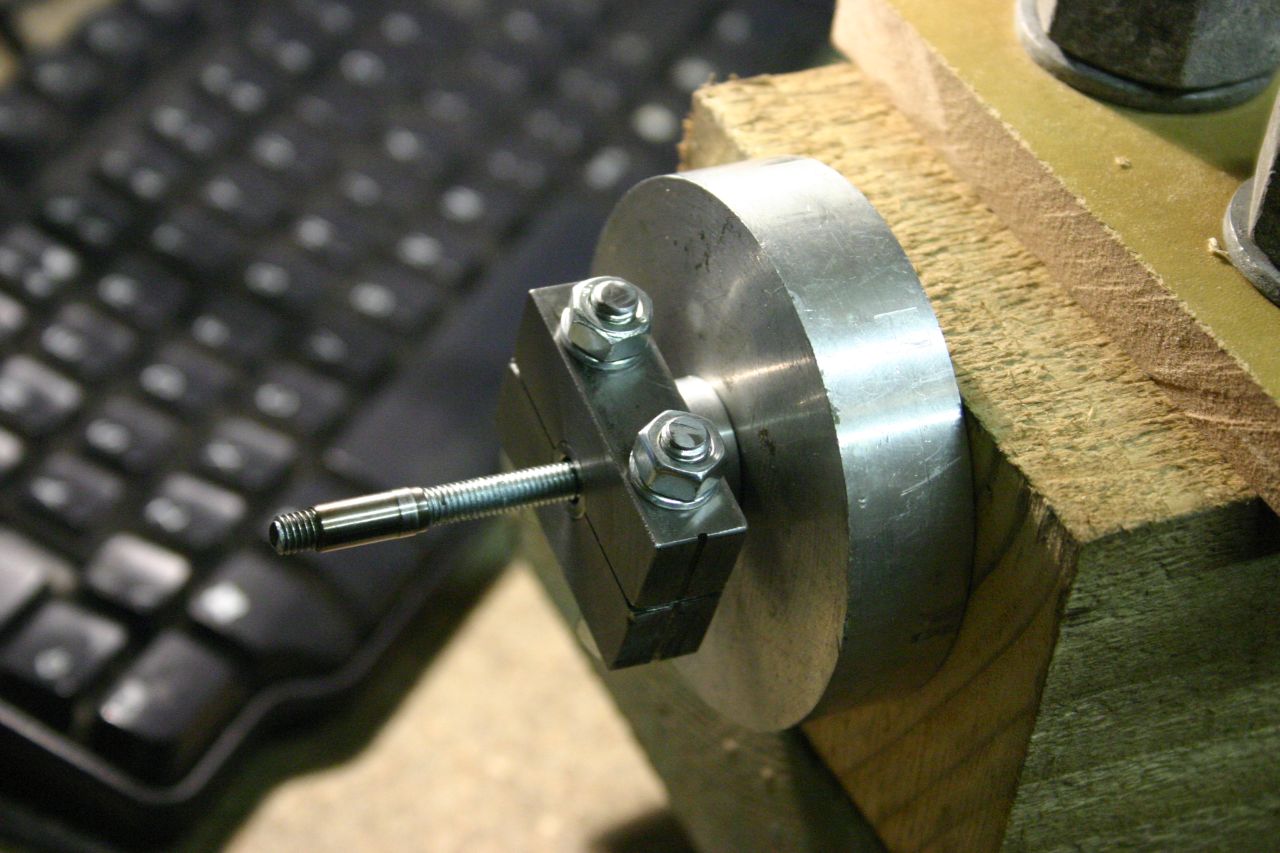 Tube clamp with support washers |
 |
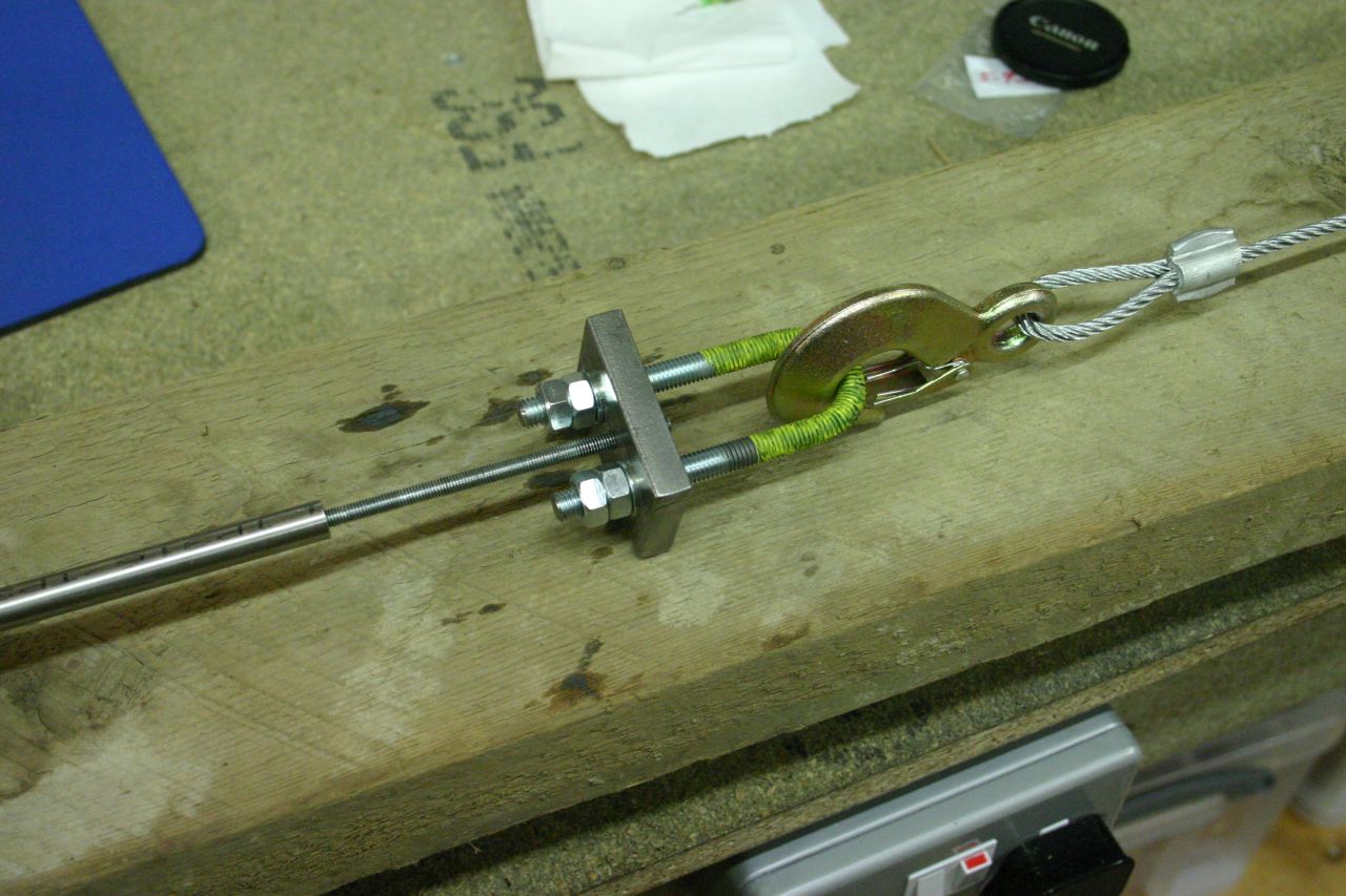 Drawbar attached to shackle |
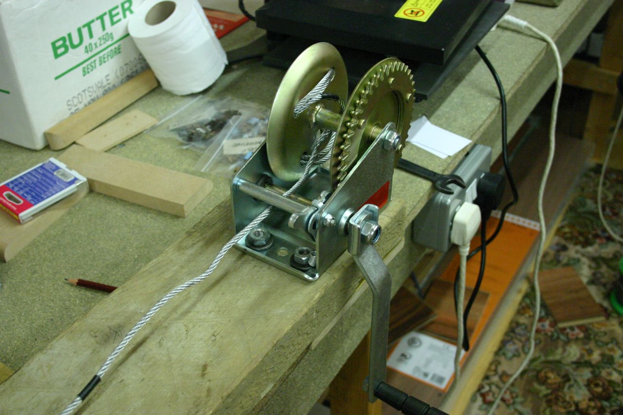 Winch |
 |
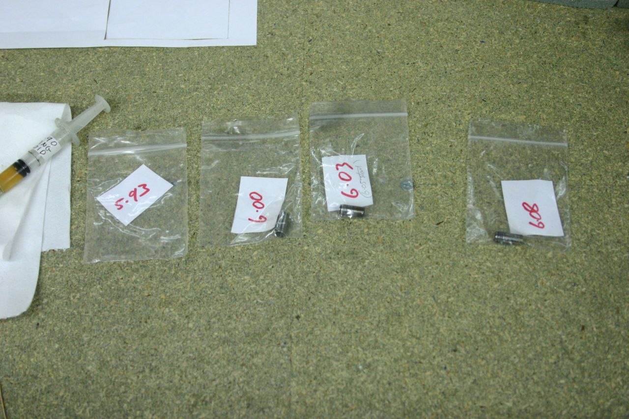 Various swaging tools |
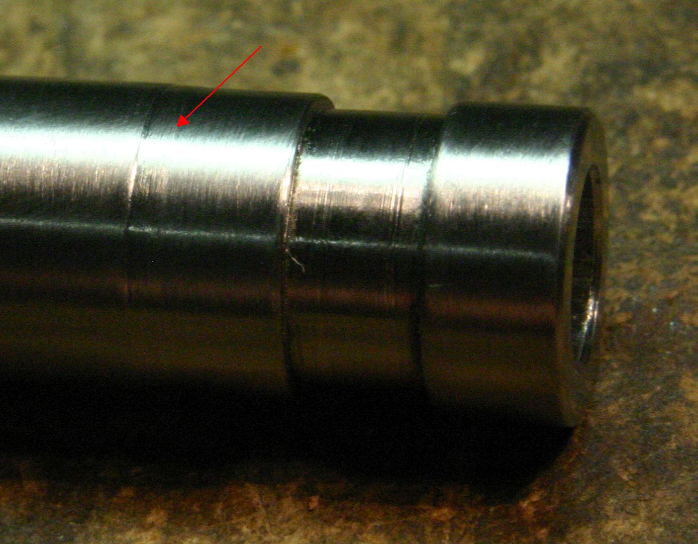 Red arrow shows where the clamp has dug into the tubing |
Here's a video of the process:
| ▲ Workshop |