
| ▲ Electronics |
I wanted a general-purpose high-voltage supply for playing around with Nixie and other discharge tubes. I had previously been using either an ancient valve-based supply, or a variac driven from the mains, neither of which was convenient.
The circuit isn't anything particular amazing. It's a boost converter based on the MC34063 chip, which is quite common in Nixie tube power supplies. Input voltage to the converter is around 28V. Total power is limited to about 20W (the limiting factor in boost converters is the output power, not voltage or current. This circuit can deliver 20W at whatever output voltage it's currently set at.)
Click here for a PDF of the circuit. A ZIP file with schematic and board files is available here.
It has since been pointed out that R3 doesn't need to have such a low resistance (and hence require high power), because of the current gain provided by Q2. Also, a couple of voltage-stabilizing resistors across the HV output caps C5 & C6 would be beneficial.
Several points to note:
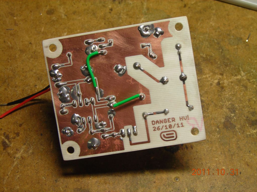
The 0.116Ω sense resistor in the power supply line is used for over-current sensing by the MC34063. Lacking a suitable value of resistor to hand, I made one using a short length of constantan wire - see here.
Since the MC34063 can only source current in this configuration, if the output is connected directly to the MOSFET gate with a 470Ω load resistor, turnoff losses are quite high. This can easily be improved by using a speedup circuit consisting of a diode and PNP transistor. The pictures below show the circuits and the gate waveform both without and with speedup.
 Without (top) and with (bottom) speedup circuit |
 Without speedup |
 With speedup |
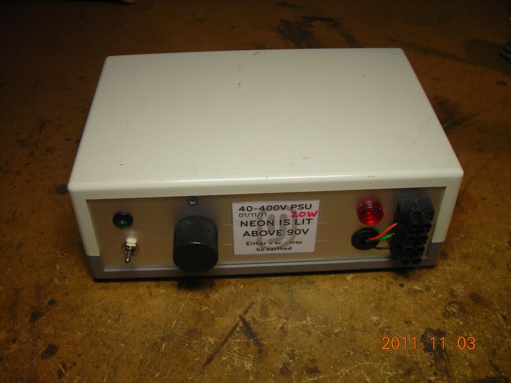
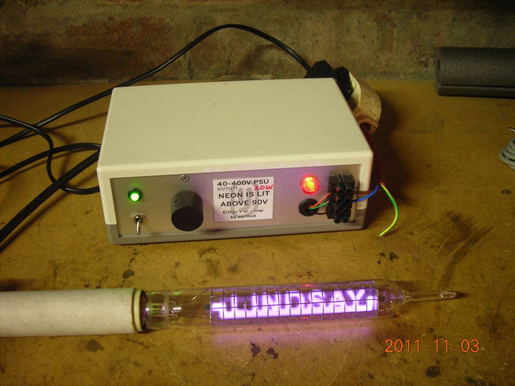
Lastly, a word about the feedback network. The MC34063 adjusts the duty cycle of its output to vary the output voltage until the voltage on its feedback pin is equal to 1.25V. In order to use a potentiometer to control the output voltage, and ensure both a linear adjustment and that the output voltage is forced low if the potentiometer wiper loses contact with the track, some trickery is required. This PDF gives an example of the feedback networks used. I initially used a single-turn 470kΩ pot for adjustment, which required modifying the pot slightly. Later, I discovered it was possible to buffer the sensed output voltage with an NPN transistor, which allowed me to use a 5kΩ multi-turn pot instead, for much finer adjustment. The end result is a nice linear adjustment from 40V to 400V.
For more details on the advantages of the grounded-wiper potentiometer feedback configuration, please see this page.
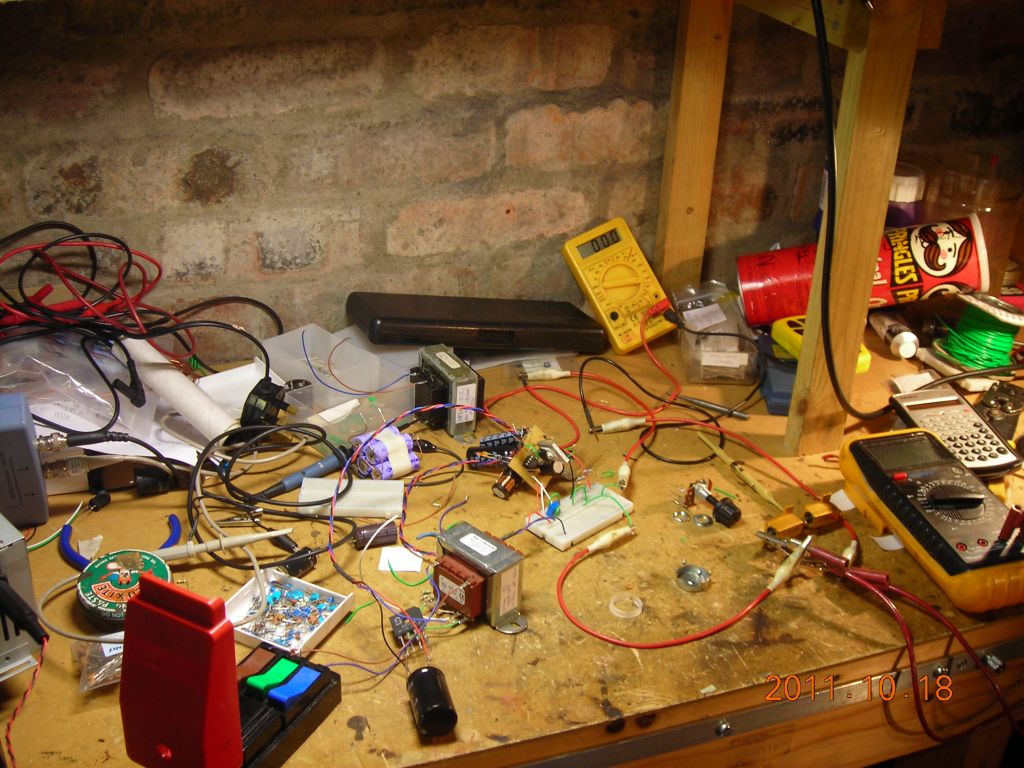
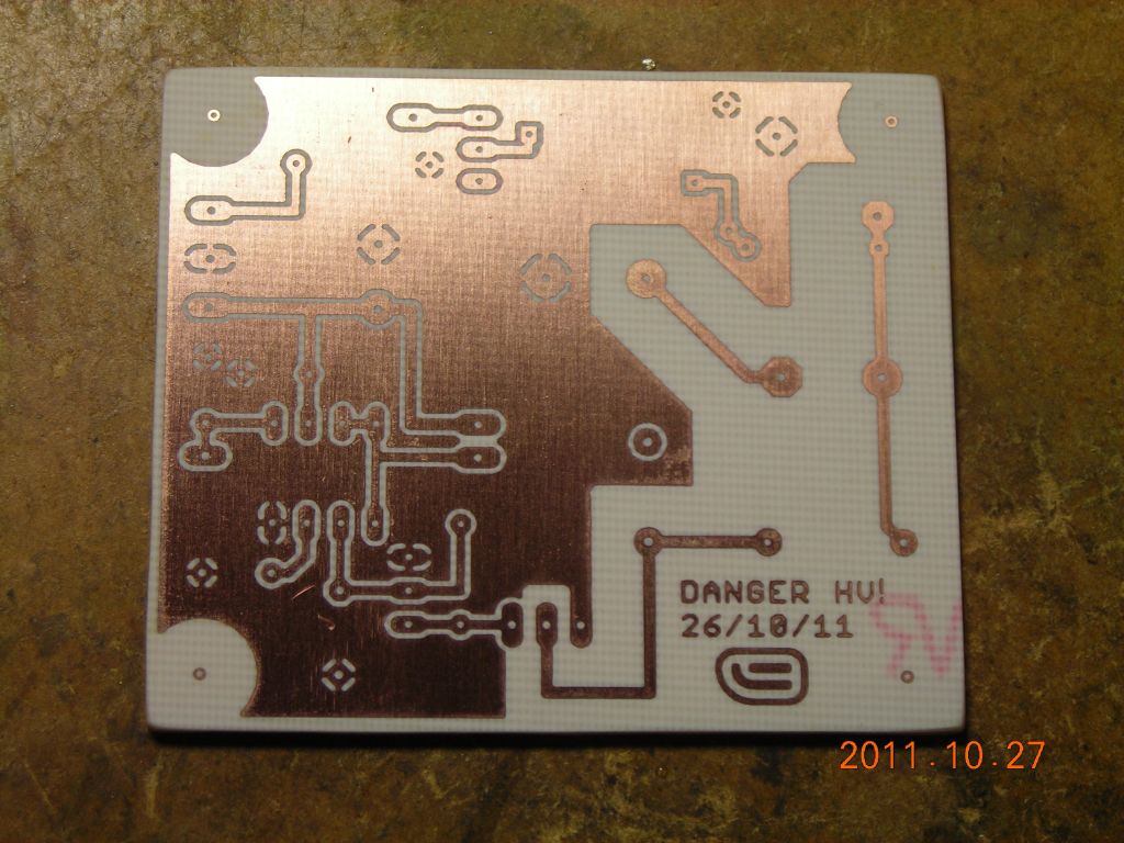
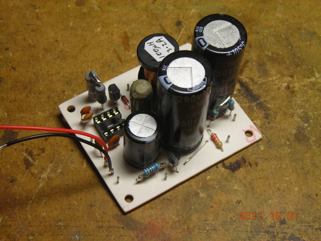
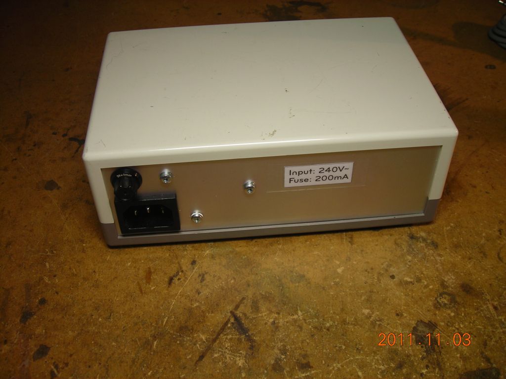
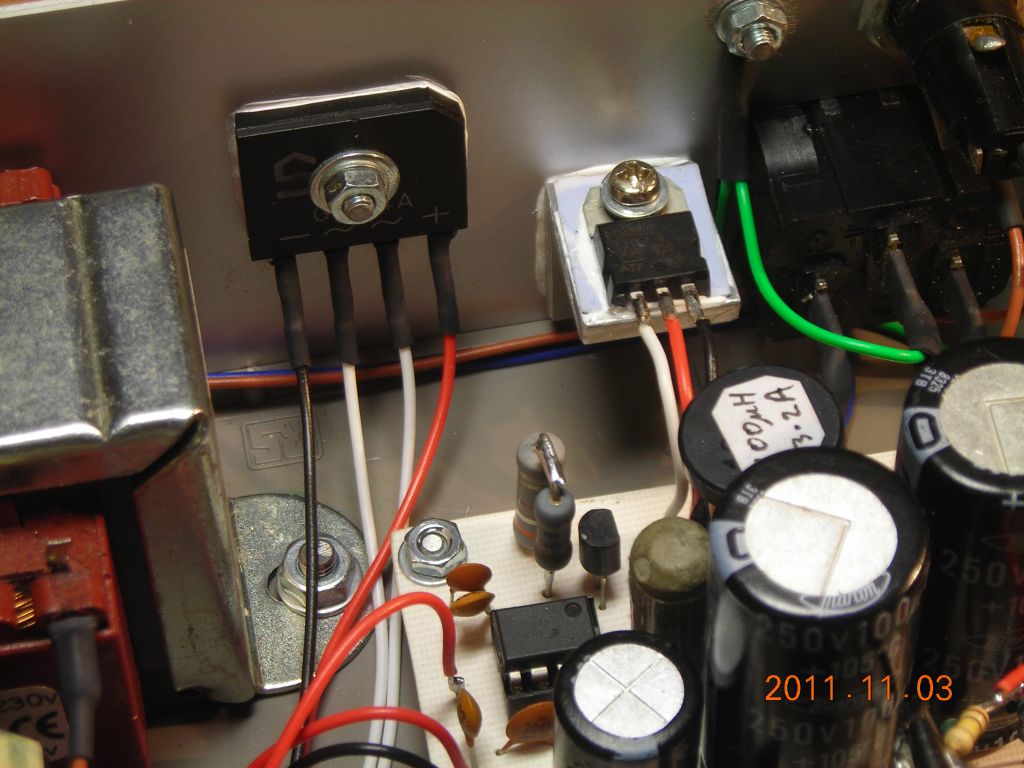
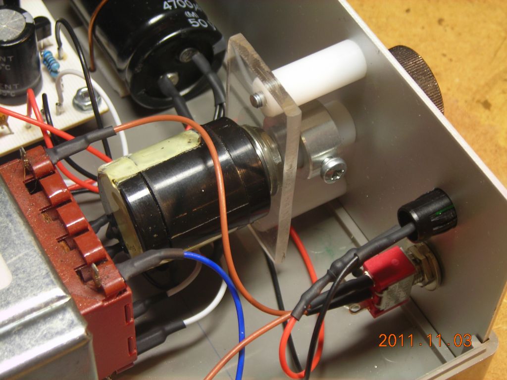
Here's some photos of the construction. I initially breadboarded it, but switchmode supplies don't take kindly to breadboards (stray inductances) so I made a lashup board for testing first, then moved everything on to a proper PCB. It was a squeeze to fit everything in the box, but it went. The output is through a terminal block at the front, and either positive or negative can be earthed.
Note the insulating extension shaft I made for the potentiometer - probably overkill, but the pot did have a metal shaft, so I thought it better to insulate it anyway.
Last pic shows it running my text discharge tube.
 |
 |
 |
 |
 |
 |
 |
 |
 |
 |
 |
 |
 |
 |
| ▲ Electronics |