
| ▲ Electronics |
I've been asked several times recently about this topic so thought I'd do a page explaining the principles. I haven't seen this particular potentiometer configuration used in power supply design, despite the clear advantages of a linear response and safety protection if the wiper loses contact with the track.
If you prefer watching a video explanation instead, see down the bottom of the page.
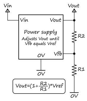
Consider a generalized power supply, shown in the figure below. It takes an input voltage, Vin, and produces an output voltage, Vout. For example, Vin could be 240VAC mains, and Vout could be 12VDC. The actual voltages and power supply topology (linear, buck, boost, flyback, whatever...) aren't relevant to the discussion.
In order to regulate the output voltage (e.g. to account for changes in load), a portion of the output voltage is sensed with a resistive divider and is fed back to the power supply. The power supply's controller compares the feedback voltage, Vfb, with an internal fixed reference voltage, Vref, and adjusts Vout until Vfb equals Vref. In practice, this could mean varying the base current to a series transistor, or varying the PWM duty cycle of an inverter. Vref depends on the controller IC used - for example, the MC34063 (which I used in my 40-400V supply) has a fixed 1.25V internal reference, whereas the common TL494 (used in many/most switchmode supplies - for example, see the one I modified) has a user-supplied reference, typically set at 2.5V.
The steady-state output voltage is given by the equation in the figure below and depends on the values of the two divider resistors, R1 & R2, and the fixed reference voltage. In an adjustable supply, the fixed resistor divider is replaced by some combination of potentiometer and fixed resistors.
A good adjustable supply has two desirable criteria:
Let's now look at four different arrangements of potentiometer feedback circuits and see how suitable they are. In all, the original circuit is shown on the left and the equivalent two-resistor circuit on the right. The small arrow next to the potentiometer symbol indicates the direction of wiper travel when the potentiometer is turned clockwise. The position of the wiper along the track is indicated by the fraction x, ranging from 0 (fully anticlockwise) to 1 (fully clockwise).
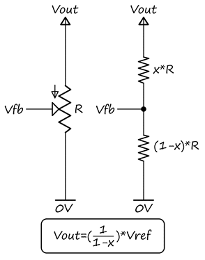
This is the simplest possible configuration. The track is connected between the output voltage & ground and feedback taken from the wiper.
Since x appears on the bottom line of the equation, the response is nonlinear. In addition, if wiper contact is lost, the feedback input to the power supply becomes disconnected and, since most feedback inputs will have a high impedance, it may float to an unknown voltage. This could be remedied with a high-value resistor directly between the feedback pin and Vout, but there are better solutions.
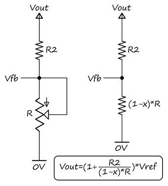
The potentiometer is now used as a variable resistor in the lower leg of the divider. Again, since x appears on the bottom line in the equation, response is nonlinear. If wiper contact is lost, this has the effect of setting the lower leg resistance to R, which results in Vout being forced to the low end of the adjustment range. This is better, but we still have a nonlinear response.
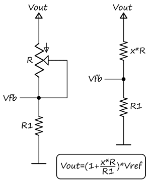
The potentiometer is now moved to the upper leg of the divider. This time, x appears on the top line in the equation, so the response is linear. However, if wiper contact is lost, the upper resistance becomes R, which forces Vout to the high end of the range - clearly not a desirable result.
Which leads us on to the final, best solution...
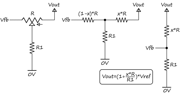
One end of the track is connected to Vout, the other end to Vfb and the wiper is grounded via lower resistor R1. This rather unusual configuration has the same voltage-response equation as the previous situation (potentiometer used as variable resistor in upper leg). In the calculation, we can generally ignore the (1-x)*R series resistance between the divider node and Vfb because the feedback pin impedance is much higher than the potentiometer resistance. Voltage response is again linear. However, this time, when wiper contact is lost, Vfb is directly connected to Vout, so the output will be forced to the low end of the range, which is a safe behaviour.
This configuration allows perfect linear adjustment from Vref to (1+(R/R1))*Vref.
The "grounded-wiper" feedback arrangement offers both linearity & protection against wiper contact loss. I don't know why I haven't seen it used in commercial supplies, but I have used it a couple of times in supplies I've built or modified.
Note that the above circuits are "bare-bones" designs - in practice, it may be necessary to add additional fixed resistors to modify or limit the range of adjustment, or capacitors to tailor the frequency response (essential in switchmode power supplies, to prevent instability, but I don't understand much about it).
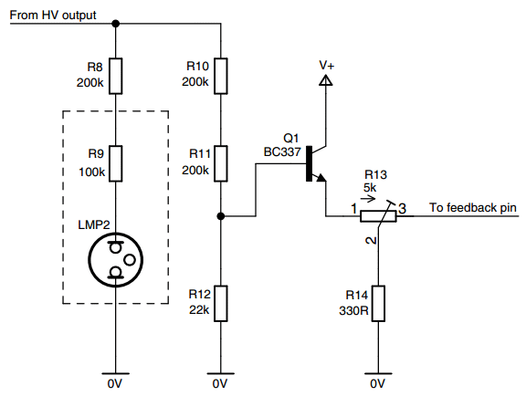
In my 40-400V high-voltage supply, I used a pre-divider to reduce the voltage applied to the potentiometer (and hence the required power rating) - this was essential because of the relatively high maximum output voltage. I used an emitter-follower transistor to buffer the output from the pre-divider and maintain linearity. Although the transistor introduces an offset voltage because of the base-emitter drop, it doesn't affect the linearity. Here's the circuit I used (more details on the main page):
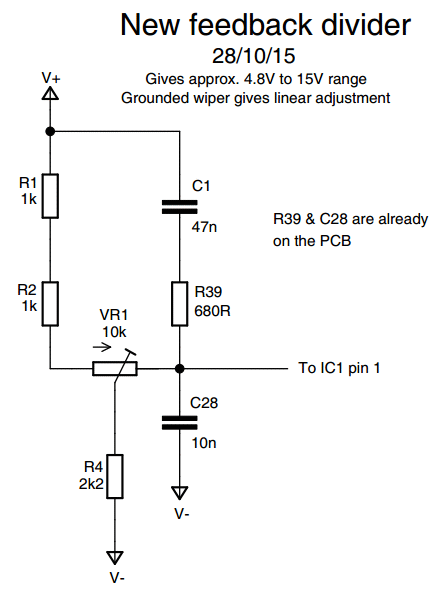
When I modified a SMPS for a variable output, I added some additional resistors and capacitors to achieve a desired frequency response and limit the voltage range. Here's the circuit used in that situation - R1 & R2 limit the lower end of the range to about 4.8V to prevent the short-circuit protection on the supply from kicking in. C1, R39 & C28 control the frequency response.
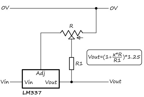
In addition to the "normal" divider orientation shown above, the same principle can be applied to "upside-down" dividers, such as that used in the LM317 adjustable linear regulator. It adjusts its output until the voltage between the output and the adjustment pin is 1.25V. For example, here's an adjustable voltage regulator:
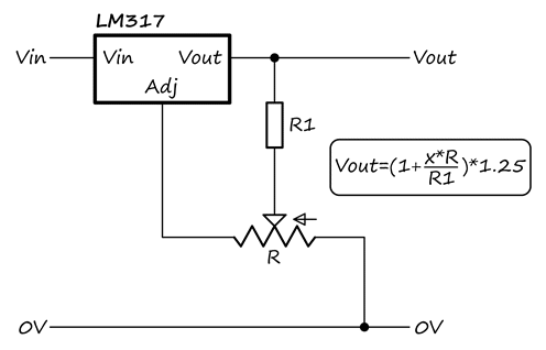
Important note: It was pointed out by a YouTube viewer that the above circuit has an unpredictable output voltage if the wiper loses contact and the output is unloaded. I tested and it gave something like 5V, rather than the 1.25V you'd expect. Best solution is to ensure there is always some load present, even a 1kΩ resistor.
01/06/17: A reader asked how the LM317 voltge regulator circuit would look if used with an LM337 negative adjustable regulator instead. The equivalent LM337 circuit is shown below - you can see how it has the same connections; I've just flipped it upside-down for ease of viewing, since that's usually now negative regulators are depicted.
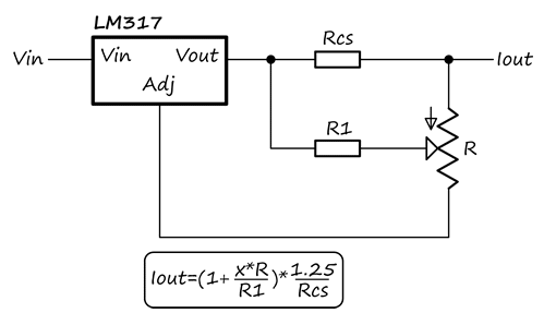
And here's an adjustable constant-current regulator. Rcs is the current-sense resistor - make sure it has a suitable power rating. For a practical example of this, see the LM317 adjustable current source I built for driving a laser diode to try some laser cutting on the AxiDraw.
Finally, here's a video covering most of the topics discussed on this page.
| ▲ Electronics |