
| ▲ Electronics |
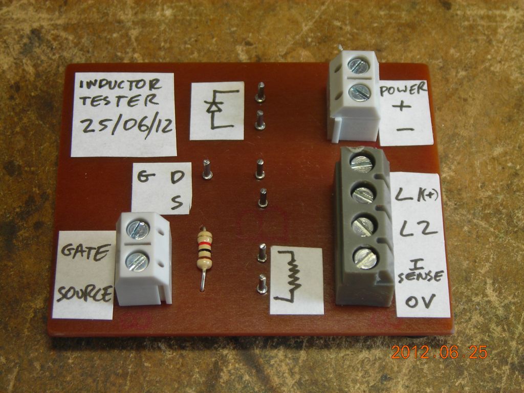
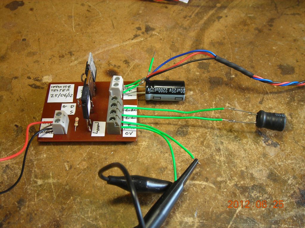
This is a simple circuit for measuring the inductance and saturation current of inductors. Driven by a pulse generator, it applies a constant voltage across the inductor and the current rise is measured using a sense resistor. The circuit is available here and is pretty simple. Q1 is a MOSFET to switch the inductor, R2 is a current-sense resistor and D1 is a catch diode to absorb the back EMF from the inductor when it's switched off. R1 (1kΩ) ties the gate of Q1 low when not driven.
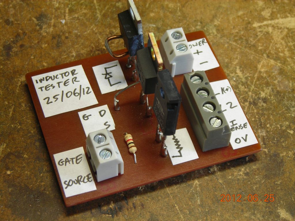
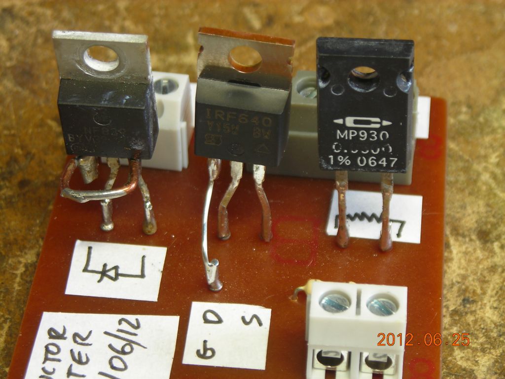
In the photos below, I'm using a IRF640 MOSFET (200V, 18A, 0.18Ω), a BYV32-200 ultrafast diode (200V, 16A) and a 50mΩ sense resistor, all driven from a 12V supply. At large currents, it's better to use a higher drive voltage and a shorter drive pulse beacuse the voltage across the sense resistor and MOSFET become significant, altering the actual voltage applied to the inductor.
The graph shows the current through a small inductor I had lying around. From the initial slope (about 1650A/s) and the drive voltage (12V), the inductance is 7.3mH, which is in good agreement with my LCR meter (7.2mH). The saturation current (the point where the current starts to increase rapidly) is around 0.4A.
 |
 |
 |
 |
 |
 |
 |
20/11/13: Here's some really good links on other peoples' inductor testers:
| ▲ Electronics |