
| ▲ Electronics |
I've always had the feeling that the default via diameters which Eagle generates are a bit on the small side. The automatically generated sizes can be controlled through Tools -> DRC -> Restring. By default (at least in my 5.6.0 version, the restring on outer vias is set to be 25% of the drill diameter, with min and max limits of 8mil and 20mil, respectively. The via outer diameter is the drill diameter plus twice the restring. For vias on home-made boards, I use a 0.6mm drill since I can use a small piece of wire to join the two sides. 0.6mm is 24mil, so the default restring is 6mil, rounded up to the lower limit of 8mil, resulting in a via diameter of 40mil.
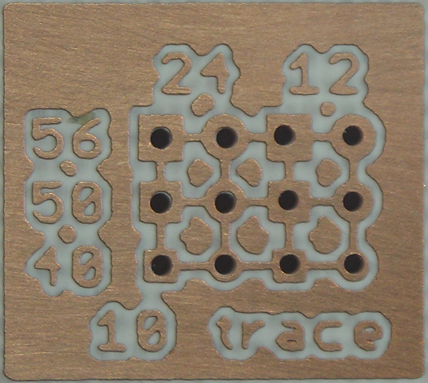
As a test, I did both square and round vias with three different diameters (40, 50, 56 mil) and two different hole diameters (12, 24 mil). The smaller hole is sometimes helpful for locating the drill bit when drilling. The vias are on a 75mil grid, and are connected with 10mil traces, the thinnest I can manage reliably. Board is double-sided and exposed using an alignment jig.
Here are 2000dpi B&W TIFF files for the top and bottom:
 |
 |
The resulting board after drilling:
 |
 |
Lastly, an animated GIF of the top and bottom:
 |
I was pleasantly surprised to see that even the 40mil dia. vias drilled perfectly and had a continuous ring of copper around them, showing no signs of tearing. The smaller hole didn't seem to help much, and possibly results in a slight burr as the drill cuts through the copper.
Conclusion? I'm probably going to use a 50mil diameter round pad, and possibly a 40mil diameter square pad if I'm really stuck for space.
| ▲ Electronics |