| ▲ Electronics |
What is a gate drive transformer (GDT)? When you have an inverter, for example an H-bridge, the upper switches (MOSFET, IGBT, whatever) in each leg are floating. Some sort of isolated drive is required. This can be implemented in many different ways, using optocouplers, DC-DC converters, charge-pumps, etc., but the simplest way is to just use a transformer. This has the added benefit of providing a bipolar drive to the switches' gates, ensuring they are held off reliably.
Side note about modern developments: Since I first experimented with GDTs ages ago, various clever gate driver chips and solutions have come on to the market, many of which would be a far better choice. They are easier to use (you don't need to wind your own transformer) and can work at any duty cycle (GDTs are mainly limited to 50%, although tricks can be used to get other duty cycles). One range I particularly like are Analog Devices' "iCoupler" range - see here for a full list of isolators. For example, the ADuM3223/4223 are dual, half-bridge, 4A drivers.
Even gate-driver optocouplers have come on a long way and very fast models are now available, for example from Avago. Charge-pump drivers are yet another option, e.g. IRF's IR2110 and related devices. However, GDTs still have an advantage where you need high drive currents, since you can use dedicated high-current driver chips (I've seen some up to 20A peak) and let the GDT worry about the isolation.
I won't go into a lot of detail about how and why GDTs are used - there is plenty of information on the web about this. For starters, I'd suggest the following:
(The last is a link to a folder on Richie Burnett's website - I don't think he ever got around to publishing these pages on his main site, but they have some excellent information.)
By far the commonest "hobby" uses of GDTs are in either Tesla coils or induction heating inverters. I first started experimenting with gate drive methods when I was messing around with an induction heater supply a few years back - for some reason, I didn't "feel" that a transformer was fast enough to suit my requirements, so I spent ages designing all sorts of ridiculous arrangements (I think about 7 different types!) before I actually tried a transformer and found it worked great.
There are various designs for GDTs going around on the web, involving different core types and wire, but I felt it would be good to try to build & characterise a few transformers with specific materials so they can easily be reproduced.
GDTs must have good coupling between primary and secondary(ies), and must have very low leakage inductance. Leakage inductance will ring with the gate capacitance, causing all sorts of problems. (For more info on the effects of leakage inductance, check out the links above). The best design is a toroidal transformer.
As far as the windings are concerned, the best way of achieving efficient coupling is to use a piece of tubular braid as the primary and insert the secondary(ies) into it. If using multiple secondaries, it's best to twist them together before inserting into the primary. Even better is to use a separate piece of braid for each secondary, but this starts getting a bit bulky. See Richie Burnett's pages for info on how the different winding types affect performance.
Every core will have a minimum number of turns to ensure that saturation doesn't occur. This will depend on the voltage applied and the operating frequency. The magnetic flux density produced in the core after applying a voltage V for a time t is given by (see here):

V is the applied voltage (for example 12V). t is the time, which corresponds to half the cycle period. N is the number of turns. Ae is the cross-sectional area of the core in m2 (obtained from the core datasheet). Rerranging this to obtain an expression for the minimum number of turns, we get:
In summary, I will be using:
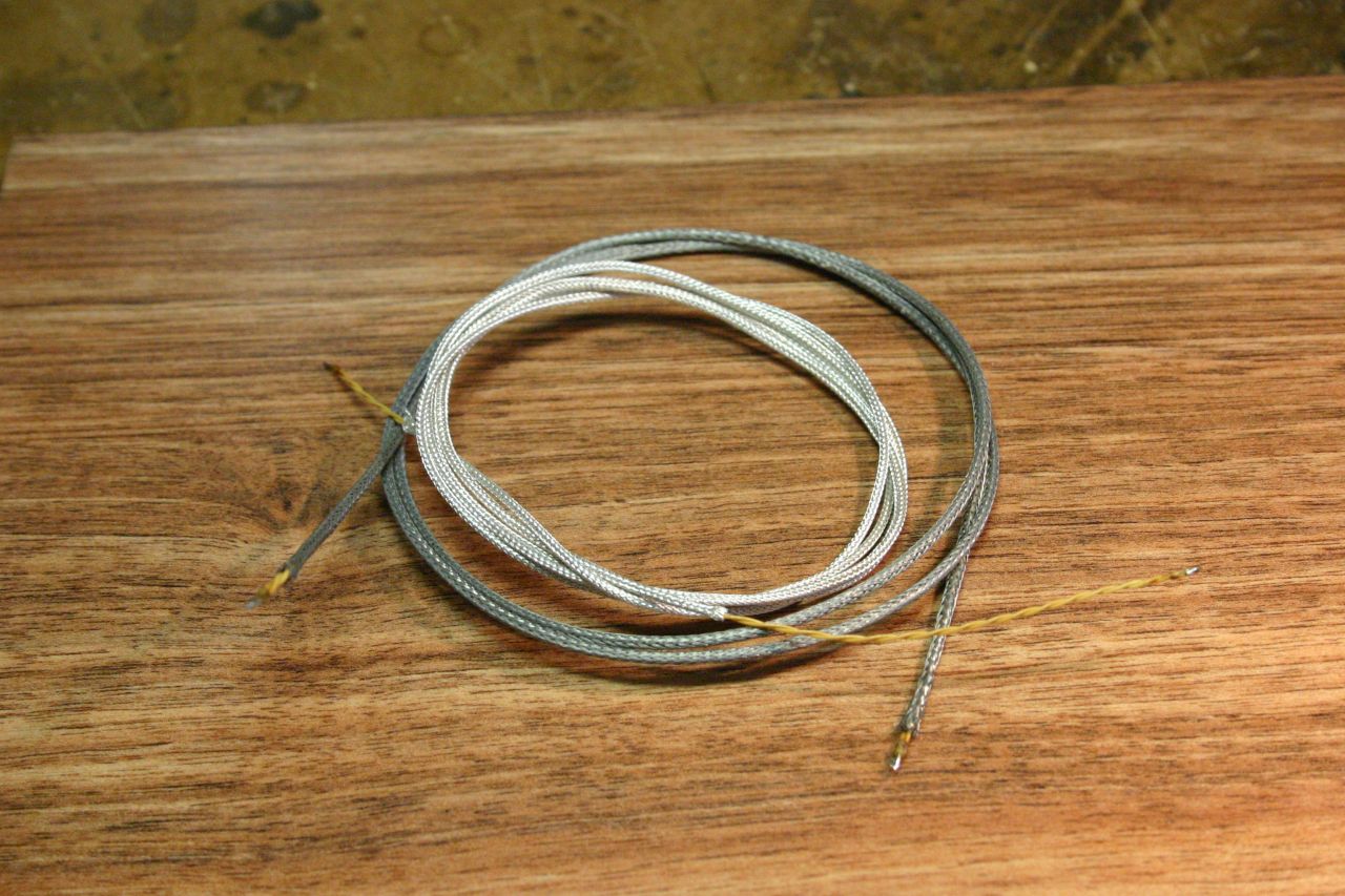
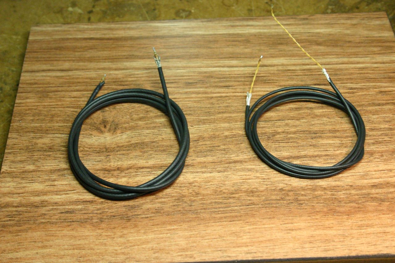
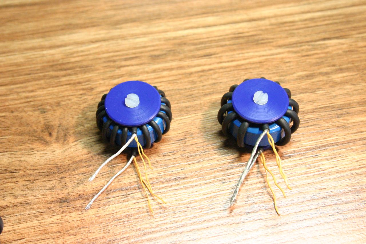
I'll be making three transformers, all with the same core, but different variations of primary and secondary windings. Here's a teaser of what we'll end up with:
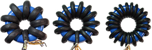
The transformer on the left, with the largest windings, was actually made a few years back when I first experimented with this. The two on the right were made for the purposes of this investigation.
Here's a summary of different materials used. Not all were used in the final three transformers - specifics are further down the page.
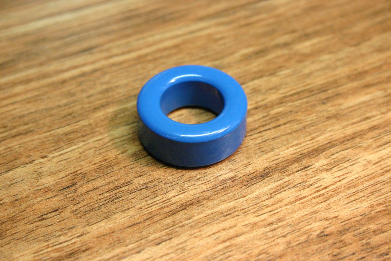
Based on the advice given here, I chose the following toroidal core:
Here's the core itself. Pretty exciting, isn't it? You can even click on the image for more excitement.
What's a typical minimum number of turns required? A safe value for the maximum flux density is 0.25T. Let's say the operating frequency is 100kHz, which is a cycle period of 10µs. The on time is half this, or 5µs. Applied voltage is 12V. The cross-sectional area (from the datasheet) is 51mm2. Substituting all this in to the equation above, we get the minimum number of turns to be about 5. At higher frequencies, we can get away with fewer turns.
I'll talk about this first. A favourite for GDT secondaries is one of the twisted pairs from CAT5 Ethernet cable, however this isn't really meant for high voltage insulation. Enamelled copper wire is acceptable, but it is possible to scratch the enamel. Besides, there is a much better solution: triple-insulated wire.
This is incredibly neat stuff. Like the name implies, it has three layers of insulation and is rated to several kV. The main advantage is in winding power supply transformers - no interlayer or interwinding insulation is needed, reducing the bulk considerably and simplifying the winding process. It's made by Furukawa and there are several different types available - I used "Tex-E". Furukawa's site is here. In the UK, the wire is available from PACE Components, who have a great online shop and also a wide selection of ferrite cores & bobbins.
I'm going to be using both 0.3mm and 0.5mm wire. When two of these wires are twisted into a pair, the approximate diameter of the bundle is:
The simplest source for tubular copper braid is coax cable. It is possible to buy braid on its own, but I could only find 100m rolls.
RG58 cable is the commonest, but the braid is a bit large for convenient use - I was only able to get 8.5 windings on the core, which was pushing the lower limit for preventing saturation at the frequencies I was working at (see next section). However, I did use it for my very first transformer and I've characterised that here.
Here are other sizes of coax cable which seem to be available:
These are all available in some form from EBay - you may have to buy a WiFi patch lead or something similar in order to get the cable. Some types are available with a silver-plated braid (especially RG178). I decided to make the two new transformers using RG174 and RG178 braid.
In summary, the three transformers will be identified by the type of primary braid used: RG58, RG174 and RG178.
The entire winding (braid + twisted secondaries inside) is enclosed in heatshrink tubing for protection. The actual size of heatshrink appears to vary between suppliers, despite being branded the same (for example, "1.6mm" 2:1 black heatshrink from Heatshrink Online is smaller than that from Rapid Electronics).
I tried various types of heatshrink with different braid/wire combinations to see what worked. Here's the heatshrink types used (except on the first RG58 transformer, where I can't remember):
RG174 braid + 2x 0.5mm Tex-E twisted bundle. OD: 1.9mm. Heatshrink results:
RG178 braid + 2x 0.3mm Tex-E twisted bundle. OD: 1.5mm. Heatshrink results:
Here are the two combinations which I chose:
Right, let's make some transformers!
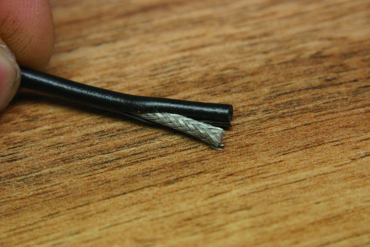
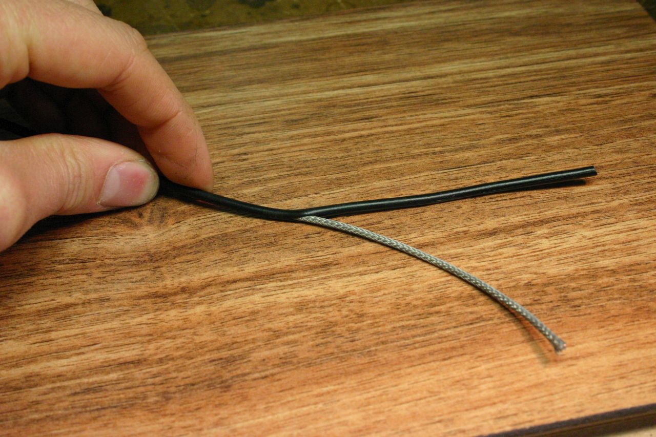
The outer insulation needs to be carefully stripped from the coax cable. I found that slitting the insulation lengthwise, but not cutting deep enough to reach the actual braid, worked well. The cut weakens the insulation sufficiently that it can be pulled off. Some photos:
 |
 |
 |
The braid will slide easily off the inner wire, but don't remove it yet.
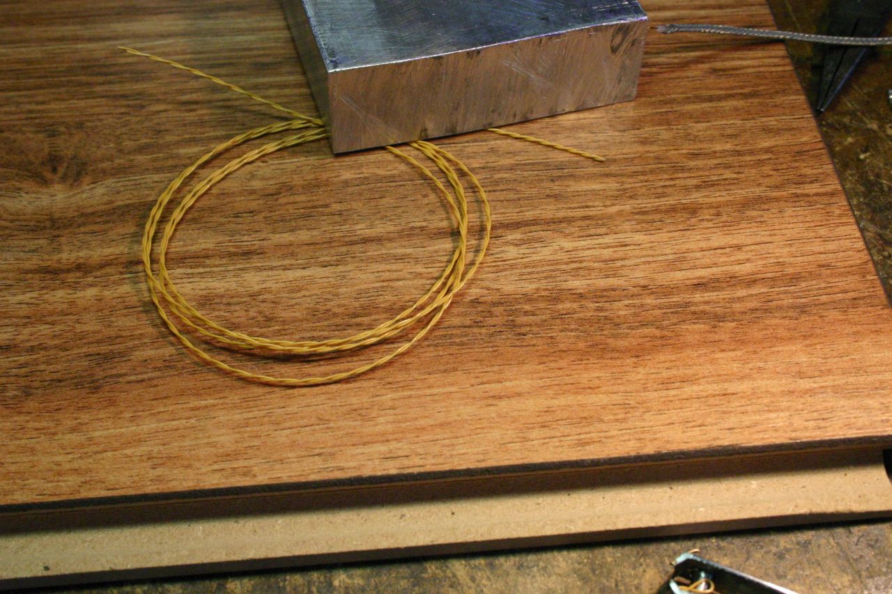
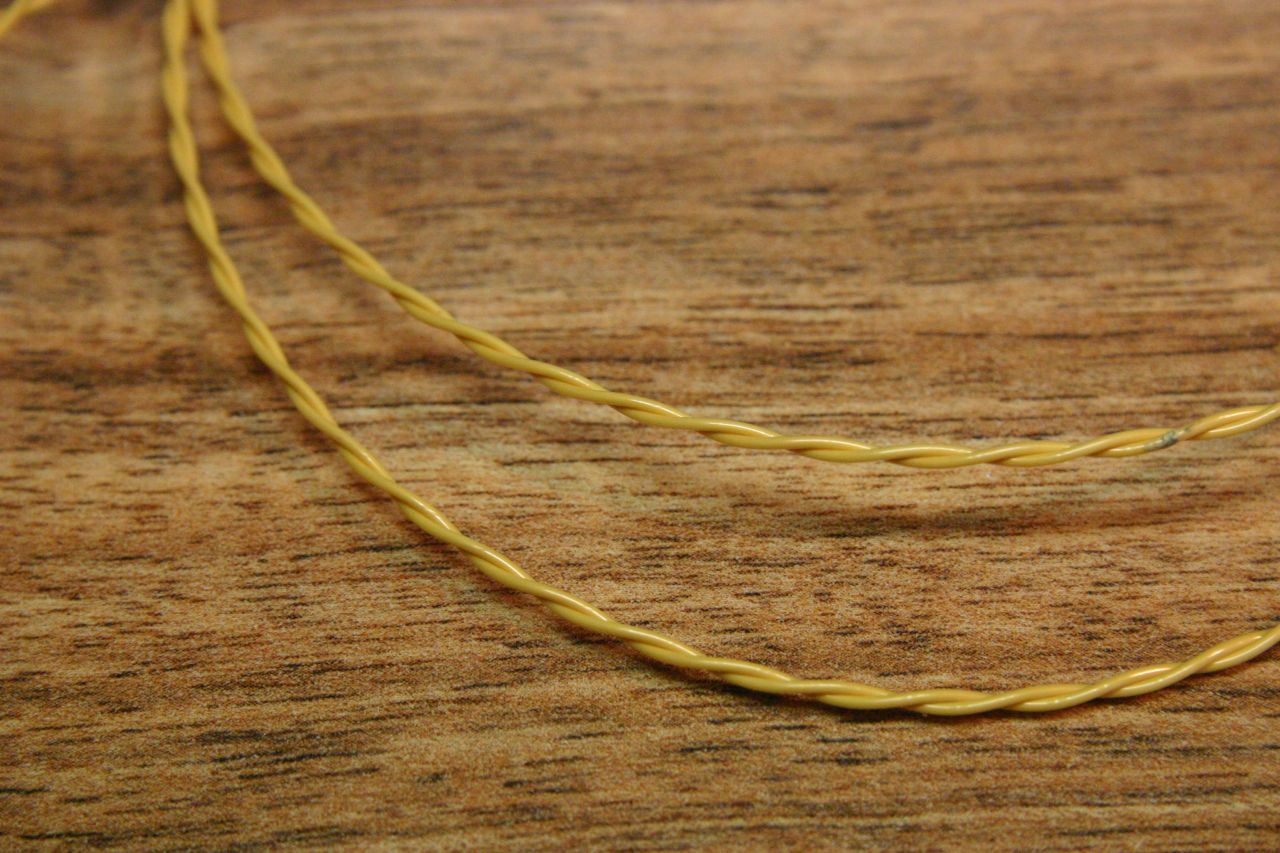
The simplest way is to take a single piece of the Tex-E wire, fold it in two, clamp the free ends in a vice, then use a cuphook in a hand drill to spin the loop and twist the wires together. They don't need to be twisted too tightly - something like 2 or 3 turns per inch is acceptable.
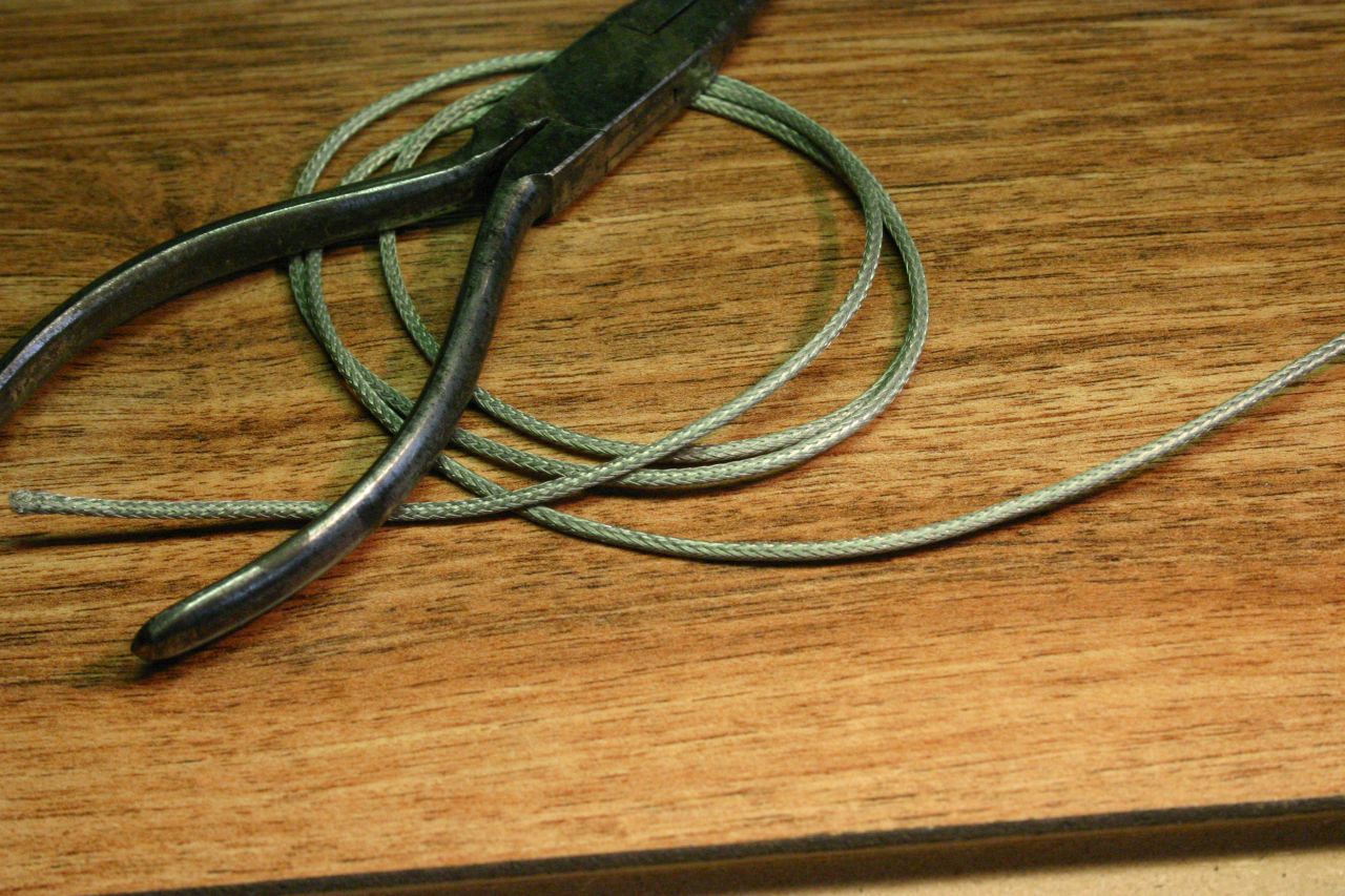
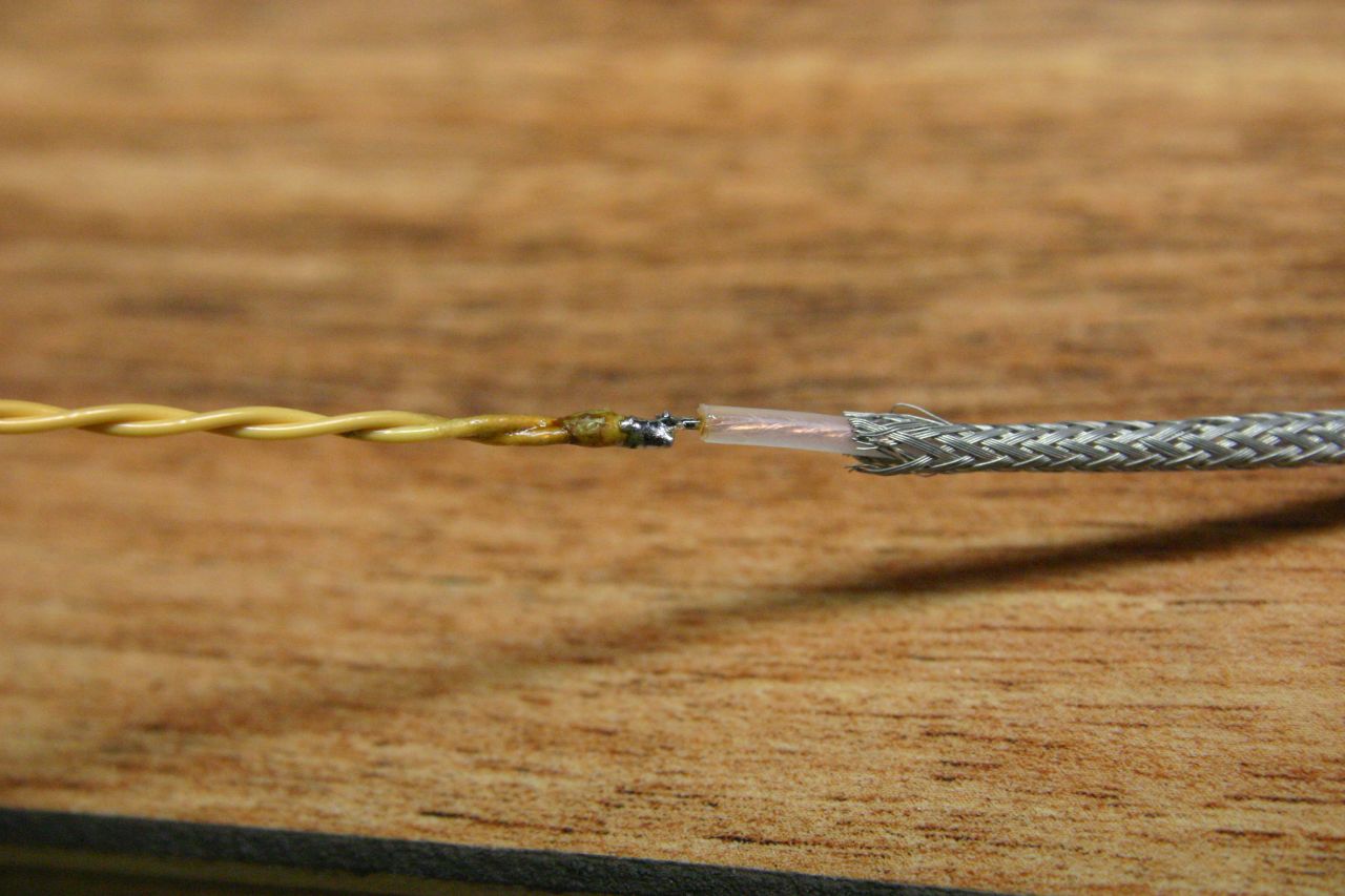
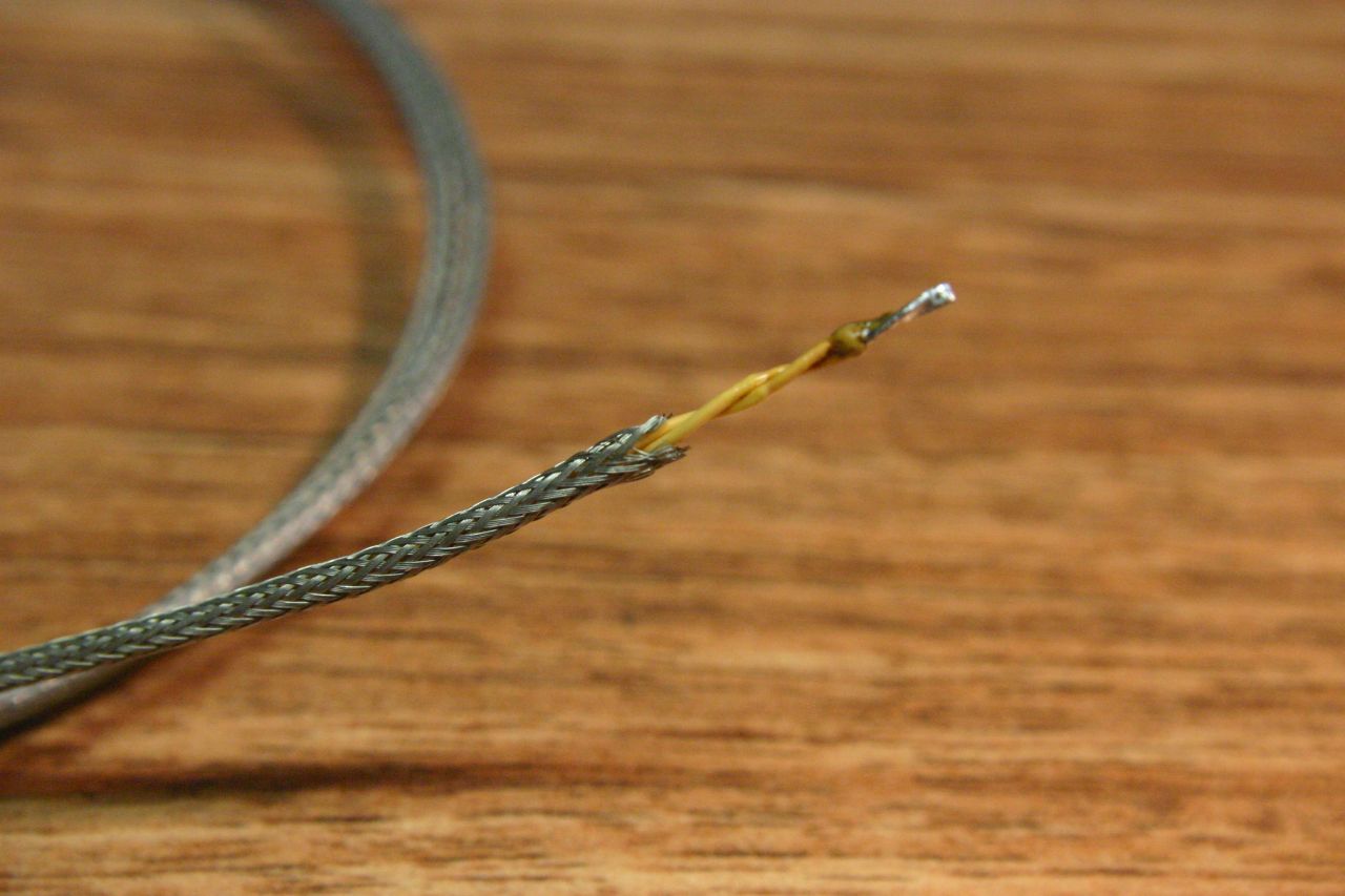
To thread the wires through the braid, I found the easiest way is to solder them to the inner conductor of the coax and use this to pull the wires through as the braid is removed. Tinning the Tex-E takes a bit of work because of the relatively thick insulation, but it is self-fluxing.
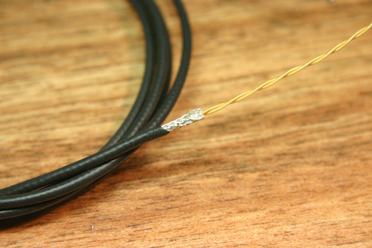
Photos (the shinier braid is the RG178, which happens to be silver-plated):
 |
 |
 |
 |
 |
The braid/wire combination now needs to be inserted into the heatshrink. For the larger braid, it could just be slid through, but the smaller braid tended to bunch up and stick. I first passed a rigid wire (1mm copper) through the heatshrink, then soldered both the braid and wires to the end of this and used it to pull the braid/wire back through the heatshrink. Once the heatshrink was roughly central on the wire, I heated it progressively from one end whilst pulling slightly to prevent any kinks.
 RG174 (left), RG178 (right) |
 Closeup of RG178 |
This is the easy part. Wind as many turns as possible on to the core - with luck, the last turn will be a tight fit and will help lock all the turns in place. To temporarily prevent the windings from springing out, push a rod through the center of the transformer as shown below.
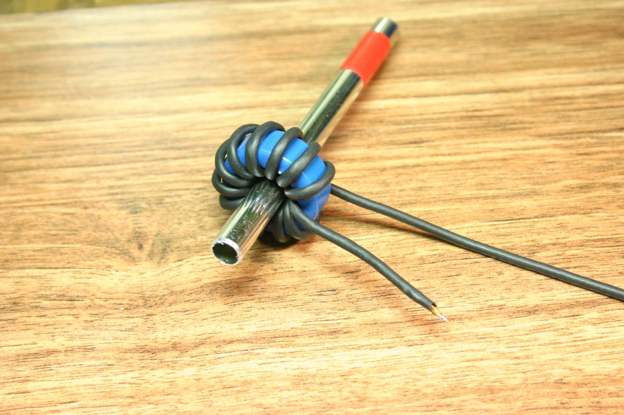 RG174 |
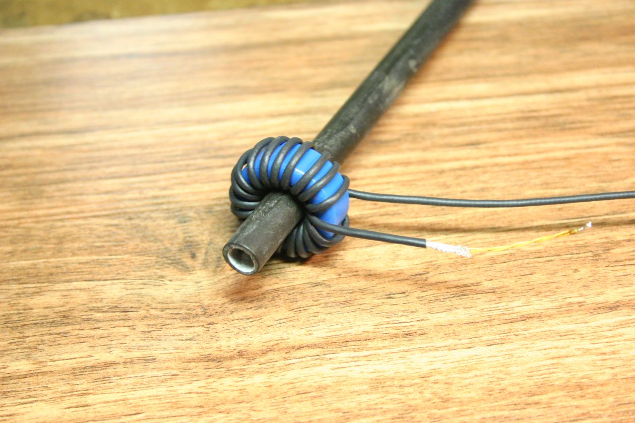 RG178 |
The windings need to be permanently secured. The quick-and-dirty way is to gloop the whole thing with hot-melt glue, but I turned a couple of plastic plugs (from blue acetal) which both keep the windings pressed out from inside the core and keep them pressed flat against the faces. It's probably a good idea to use a plastic screw - a metal screw shouldn't, in theory, affect anything since the flux is contained within the core, but you never know.
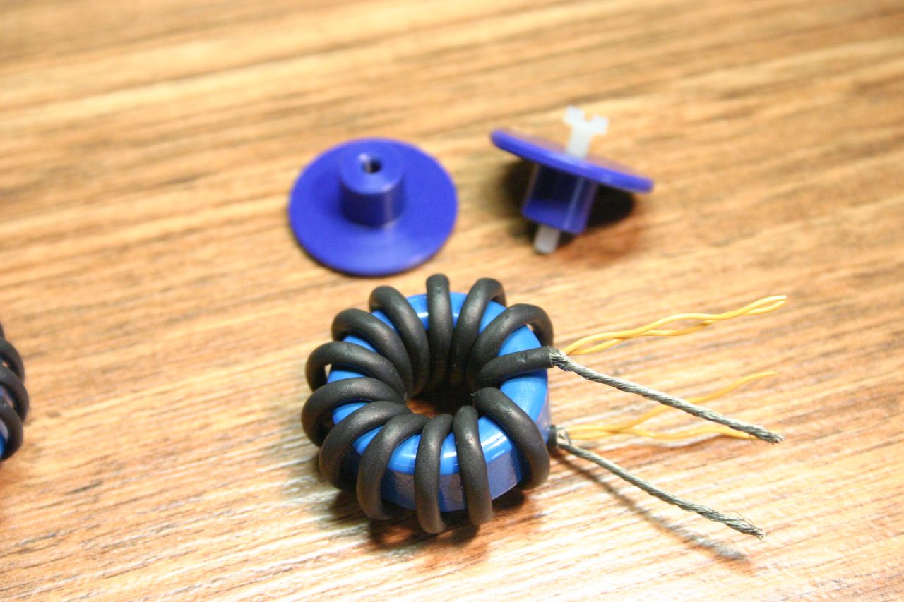
Cut the wires to length, strip off excess heatshrink, and tease out the braid to form the primary connections. Here's the finished transformers:
 RG178 (left), RG174 (right) |
 RG174 with plugs |
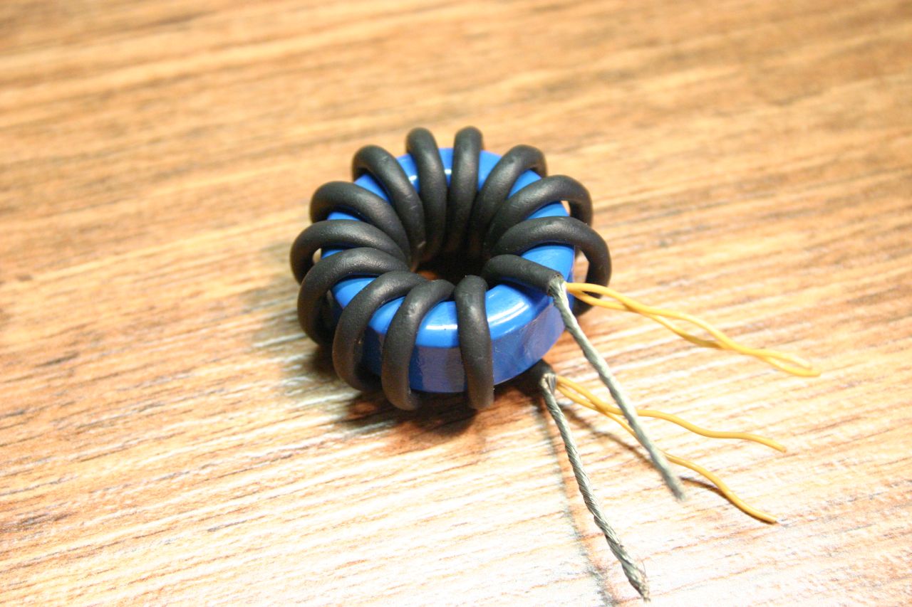 RG174 |
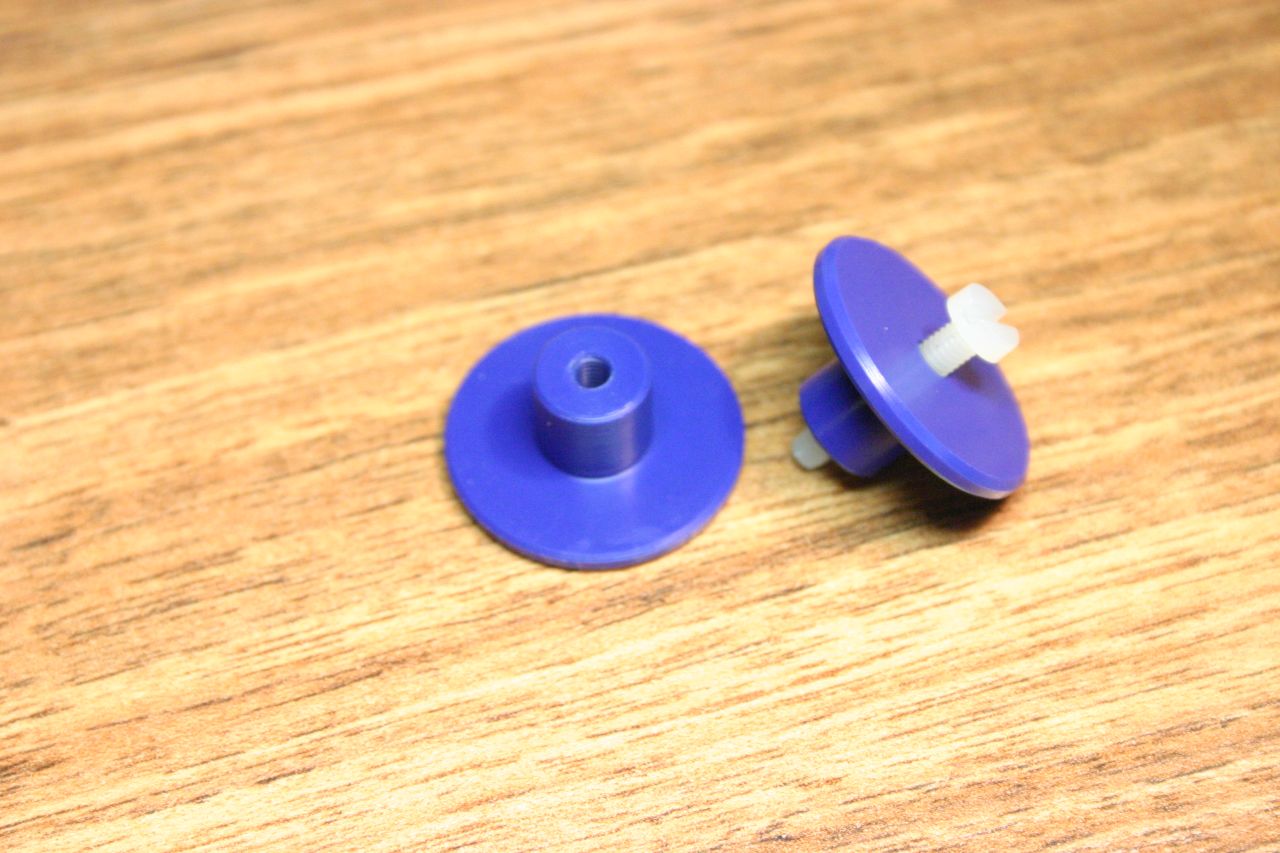 Plugs |
Overview of how different transformer properties are measured.
There is an excellent application note from ON Semiconductor which deals with models for both single- and dual-secondary transformers. Pages 4 to 6 are most relevant. Here is the dual-secondary transformer model (Fig. 11 in that app note):
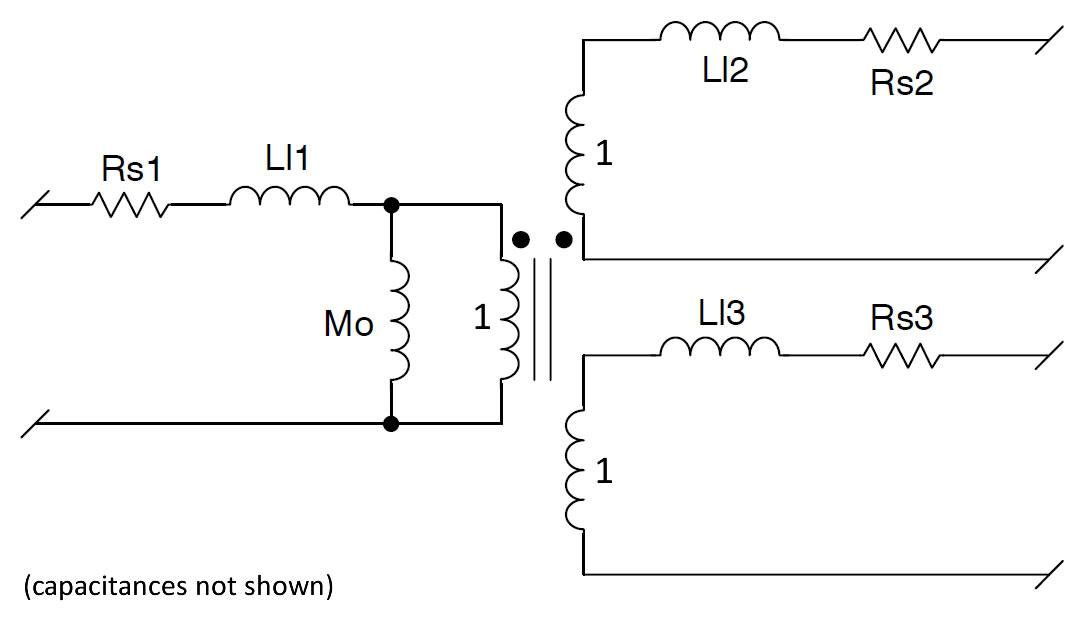
Rs1, Rs2, Rs3 are the DC resistances of each winding. LI1, LI2, LI3 are the leakage inductances of each winding. Mo is the magnetising inductance of the primary winding. Transformer action is represented by an ideal transformer in the middle.
Determining the leakage inductances requires a bit of computation. The procedure is described on page 5 of the app note. Four inductance measurements need to be taken and are called L1, L2, L3, L4:
Note that, for an identical 1:1:1 transformer ratio, like we have here, L2 and L3 are equal. Similarly, although the application note refers to "power" and "auxiliary" windings, these are simply the two (identical) secondaries.
Once these four inductances have been measured, the magnetising and leakage inductances can be calculated using the four equations on page 6 of the app note.
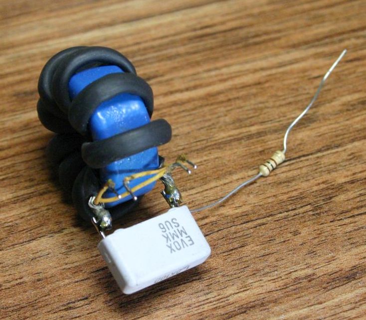
I have a little Atlas LCR meter, but this can't measure inductances in the nH range, which is what is needed for leakage inductance. Instead, I'm using the parallel resonant method of measuring inductance. The unknown inductance is resonated in parallel with a known capacitance and the inductance worked out from the resonant frequency. Here's the circuit:

A 100Ω series resistor and a 1µF resonant capacitor are used. The oscilloscope monitors both the applied voltage and the voltage across the parallel tank. When these are in phase, the circuit is at resonance and the inductance is calculated from:

Care is taken to minimise the inductance between the capacitor and the unknown inductance (leakage inductances are in the tens of nH range, so any lengths of wire can have a significant effect). The capacitor is soldered directly to the winding being measured:
When shorting out windings to measure leakage inductance, they are soldered together, again as close to the transformer as possible.
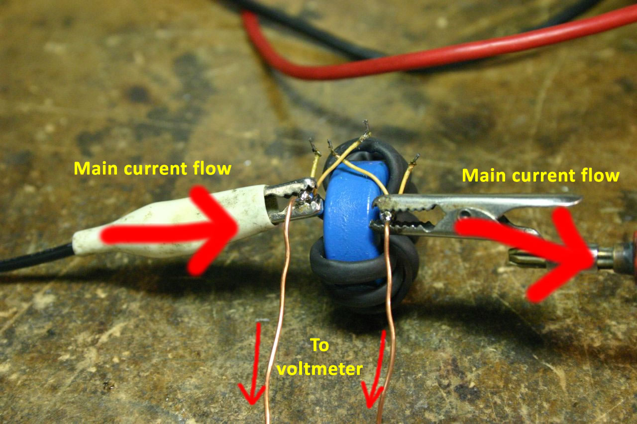
Resistances are typically in the mΩ range. I used a 12V supply with a 15Ω power resistor in series to pass a known (measured) current through the unknown resistance, then simply measured the voltage developed across the resistance. Ohm's law does the rest.
It's best to use a four-point (Kelvin) connection to eliminate errors caused by contact resistance. Two connections are used to connect the resistor to the current source, and another two connections used to connect the voltmeter. Here's the setup, measuring the resistance of the primary winding:
I simply used my Atlas LCR meter to measure this - connect the probes to the two windings in question. Capacitances are 50-200pF, so easily measurable. I found that adding interwinding capacitance to the model slowed the simulation down hugely, so didn't do it.
A measurement of the saturation current of the primary winding gives an idea of the minimum frequency the transformer can be used at. To measure the saturation current (and inductance vs. current graph), I used my little inductor tester circuit again.
Measurements were taken of both the inductor current and the voltage across it (by measuring the signal at both ends of the inductor and taking the difference) during the pulse. After some cleaning (adjacent averaging, time shift, baseline subtract, etc.), the current vs. time curve was fitted with the following expression:
This provides quite a good fit to the measured data - the curve starts off linear then increases as the core saturates (accounted for by the exponential term). I0 should be zero, but sometimes there is a slight offset in the data. The derivative curve can then be obtained:
Since we also know the voltage across the inductor, the inductance can be calculated. The saturation point occurs when the inductance starts dropping with increasing current - I chose a 10% drop, but it is open to some interpretation as the drop is gradual.
Using the above measurement techniques, I characterised the three transformers constructed earlier. The results are listed in the table below. The transformers are identified by the type of primary braid used - RG58, RG174, RG178.
| Name: | RG58 | RG174 | RG178 |
| Photo: | 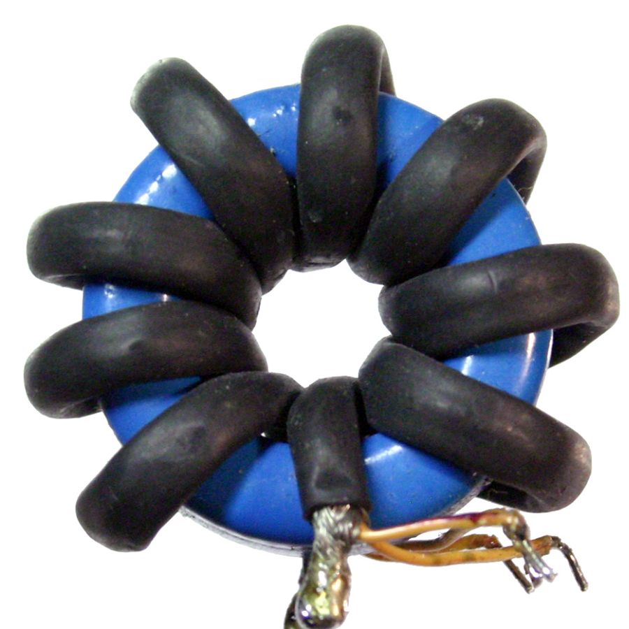 |
 |
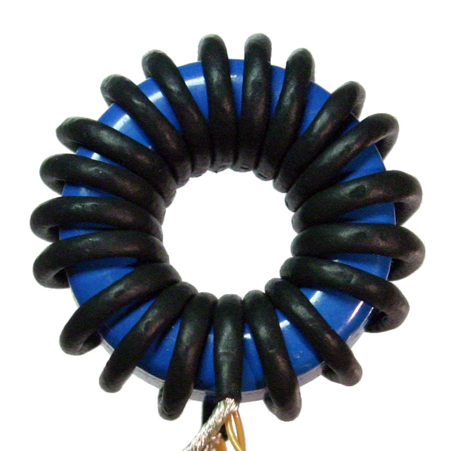 |
| Number of turns: | 8.5 | 12.5 | 19.5 |
| Primary braid: | RG58 | RG174 | RG178 |
| Primary heatshrink (both Rapid Electronics 2:1 ratio black): | ? | 2.4mm | 1.6mm |
| Secondary wire (Tex-E): | 0.5mm pair | 0.5mm pair | 0.3mm pair |
| Total winding length inc. 5cm tails: | ? | 54cm | 71cm |
| Meas. primary L, both secs open: | 451µH | 1081µH | 2284µH |
| Meas. primary L, one sec. short, other open: | 133nH | 196nH | 337nH |
| Meas. primary L, both secs. short: | 83nH | 119nH | 183nH |
| Meas. sec. L, other short, primary open: | 205nH | 320nH | 652nH |
| Calc. primary magnetizing inductance: | 451uH | 1081uH | 2284uH |
| Calc. primary leakage inductance: | 30.5nH | 36nH | 11nH |
| Calc. secondary leakage inductance: | 103nH | 160nH | 326nH |
| Primary resistance: | 5.6mΩ | 21mΩ | 37mΩ |
| Secondary resistance: | 33mΩ | 48mΩ | 194mΩ |
| Primary-to-secondary capacitance: | 54pF | 106pF | 176pF |
| Secondary-to-secondary capacitance: | 37pF | 68pF | 177pF |
| Inductance vs. current and current vs. time curves: |  |
 |
 |
| Saturation current (10% drop in L): | 142mA | 142mA | 75mA |
| Time to reach saturation current with 12V applied: | 5µs | 9.8µs | 13.2µs |
| Minimum operating frequency assuming 50% duty: | 100kHz | 51kHz | 38kHz |
(Note the identical saturation currents for the RG58 and RG174 transformers. I'm not sure why this is. Although inductance, and saturation current should be a simple function of the number of turns and the core volume, in practice this isn't the case, so I can only assume that something like this is happening, i.e. voodoo I don't understand.)
Measuring the properties is all very well, but how do the transformers behave in an actual gate-drive application? Let's find out (admittedly, I won't be driving an actual gate, but rather a 10nF capacitor which is a pretty fair approximation).
Here is the driver circuit I'll be using:
It uses a couple of UCC37322 driver ICs (9A peak current capability) to drive the transformer primary in a push-pull mode. XOR gates (74**86) are used to provide inverted signals for each driver. A series DC-blocking capacitor (C8 and C6 + C7) is used to prevent DC current flowing through the transformer.
I used a small PIC microcontroller (PIC12F615) to produce the drive signals. It produces a 25-cycle burst of pulses at about 70kHz on GP0 and an enable signal on GP1. The purposes of these will become apparent later.
Here's some photos of the test setup. The breadboard has the PIC micro and a 5V regulator. The stripboard contains the actual driver circuit. You'll notice that the stripboard actually has space for two GDT drivers (i.e. 4 driver ICs) - however I'm only using one driver channel. (The board is a leftover from when I was mucking around with induction heaters.)
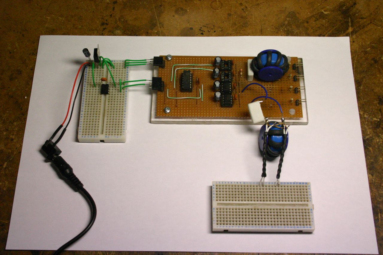 Overall view |
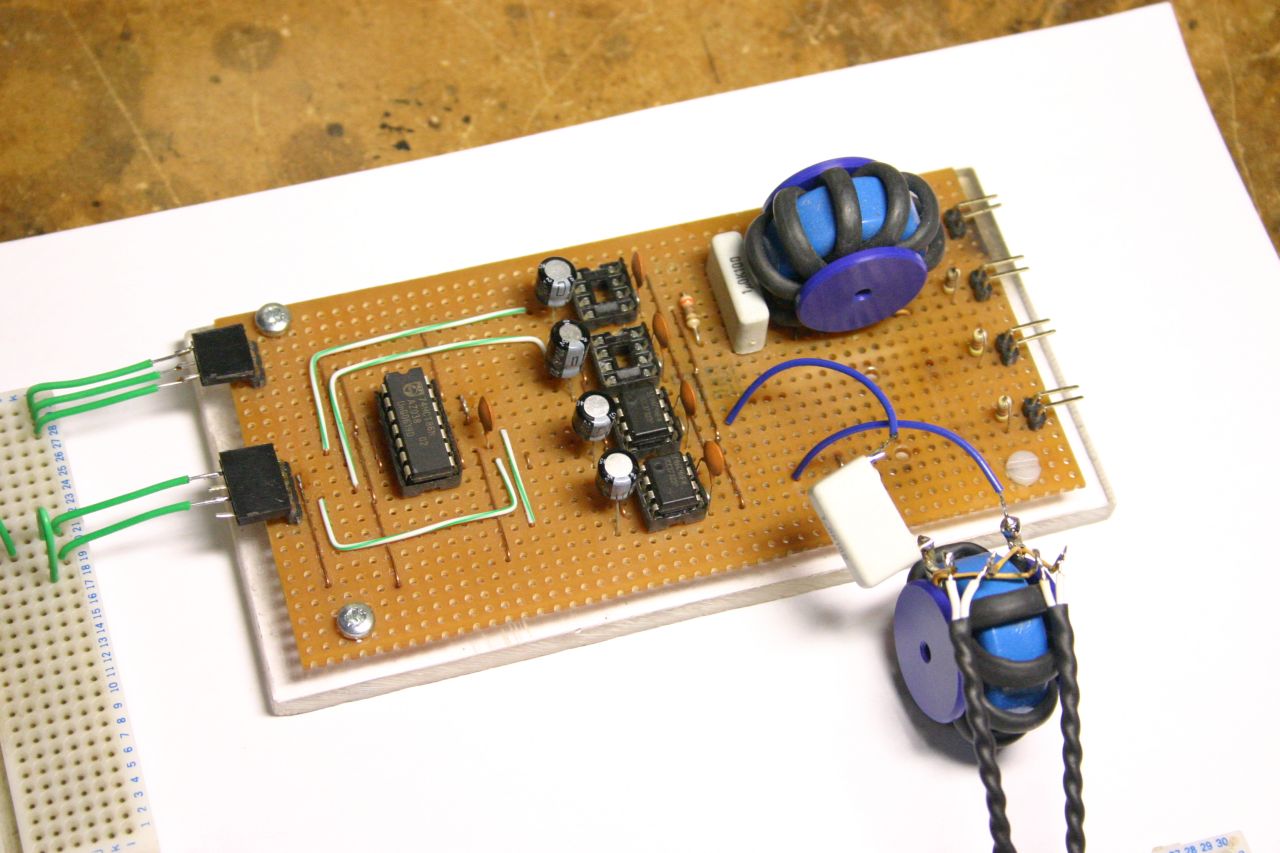 |
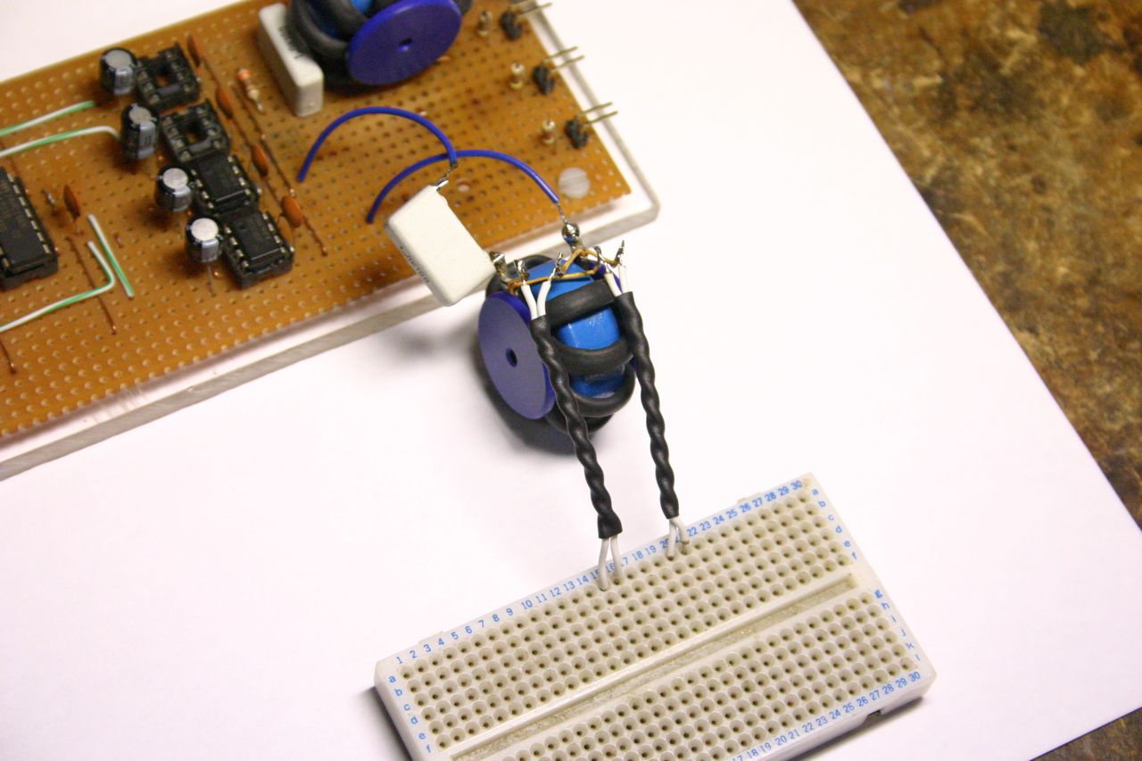 Transformer under test |
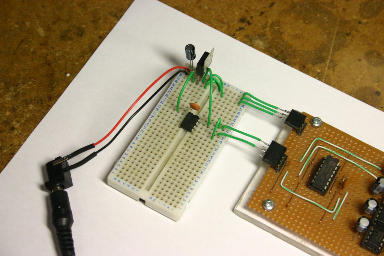 Power supply, 5V regulator, PIC microcontroller |
For what it's worth, here is an LTSpice model file for the complete gate driver. The stuff at the left is a pair of push-pull drivers (simulating the two driver ICs) with an enable input.
I first wanted to see how best to apply the drive signals, in particular how best to enable/disable the driver. If the enable input is left high but there are no pulses present at the signal input, then the outputs of the two driver ICs will be high and low, causing the DC blocking capacitor to charge up to the full supply voltage (12V). When pulses are finally applied to the signal input, the voltage applied to the transformer primary will initially be twice the supply voltage, which could possibly cause damage to the MOSFET gates connected to the secondaries! So, the enable input can't simply be left high permanently and the clock pulses applied as required; the enable input must be brought low whenever clock pulses are absent - this ensures that both driver IC outputs are held low and the DC blocking capacitor is discharged.
The waveforms below show the two different driving techniques. The upper two traces are from the PIC micro, and the bottom three are measured at one of the transformer secondaries (unloaded).
The upper two traces show the signals produced by the PIC microcontroller. The middle trace is obtained by tying the enable input high permanently and applying clock pulses to the signal input of the driver circuit. You can see how the initial half-dozen pulses easily reach over 20V before settling down. In addition, there is a large, slow oscillation after the burst ends.
By contrast, the next trace down is obtained by connecting the enable signal from the PIC to the enable input of the driver circuit, so it is only enabled during the pulse. Clearly, the waveform produced is much better - it maintains a constant amplitude throughout the pulse and ringing is greatly reduced at the end.
These two traces were obtained with only a 1µF film DC blocking capacitor. While this is probably sufficient, the slow ringing at the end of the pulse is nearly 1V in amplitude. Increasing the size of the DC blocking capacitor reduces this dramatically - I added a couple of back-to-back 22µF electrolytics in parallel with the 1µF film, resulting in the last trace which exhibits greatly reduced ringing after the end of the burst.
Let's take a closer look at the low-frequency ringing at the end of burst, described briefly above. The graphs below compare the ringing with both a 1µF cap on its own and in parallel with 2x 22µF electrolytics in series (refer back to the circuit diagram above to see the connection). With only the 1µF film capacitor, the ringing reaches 1V which, although probably isn't anywhere near the switching threshold of the MOSFET, is quite significant. When the larger capacitors are added, the ringing decreases to a few hundred millivolts, a perfectly safe level.
Now that we've settled on a suitable driving technique, let's have a look at the waveforms when a capacitive load is connected to the transformer output.
The graph below shows the waveforms obtained across different loads connected to the output of the RG58 transformer. The second graph is a closeup view of the rising edge, showing the effect of a series resistor on the overshoot. Connecting a capacitive load directly to the transformer leads to ringing (due to the leakage inductance of the transformer). This can easily reach dangerous levels - for example, the 10nF load rings up to 20V, which is the gate breakdown voltage for some MOSFETs. A series resistor of a few ohms is sufficient to bring the ringing down to safe levels, whilst not affecting the switching time significantly.
Some sources say to also use a low-value resistor in series with the transformer primary to reduce primary ringing. However, I don't exactly see the point of this since (thanks to transformer action) ringing caused on one winding can effectively be damped by a series resistor used on another winding. If you are already using a series resistor on each of the secondaries, this will damp any primary ringing as well. Besides, the power dissipation can be significant. In very general terms, the power dissipation in the secondary-side resistors is at most a few hundred mW, but the primary-side resistor can approach 1W. Personally, I'd leave it out.
Power dissipation in the series resistors is something to watch out for when designing the gate drive. I'd highly suggest you do a simulation of the actual component values you're using to verify the power dissipation. For high drive frequencies (in the several hundred kHz range), they can easily dissipate 0.5W to 1W of power. In fact, I suspect this is one reason that a previous attempt at a gate driver failed - I had used 0.25W resistors, but they burned out.
Here are the 10% to 90% level switching times for different loads:
The series resistance was chosen to obtain a critically damped waveform. Extra resistance will slow down the switching.
With switching times of max. a few hundred nanoseconds, this arrangement is easily suitable up to a few hundred kHz.
Finally, we'll look at how the different transformers behave with exactly the same load (10nF capacitor + 3.3Ω series resistor).
The first graph shows the overall waveform obtained from each of the three transformers. The only visible difference between them is the droop at the top and bottom of the waveform. As the magnetising inductance increases (going from RG58, to RG174, then RG178) the amount of droop decreases, since the magnetising current is less.
Here's a closeup of the rising edge of the waveform. There is no appreciable difference between the transformers.
Lastly, here's a magnification of the droop at the top of the waveform. Ignoring the initial resonant spike, the droop decreases from nearly 2V for the RG58 transformer to around 0.5V for the RG178. The droop isn't significant for any of the transformers, since the drive voltage always remains well above the gate threshold voltage. However, this is something to be mindful of when working at lower frequencies or with smaller (low inductance) transformers.
Hopefully, this has demonstrated some of the techniques behind the construction and characterisation of gate driver transformers. Some of the methods used will be equally applicable to other kinds of transformer.
Although GDTs are possibly less convenient to use than dedicated driver ICs (as described in red at the top of this page), they do have applications where good isolation and high-current drive are required.
| ▲ Electronics |