| ▲ Optical |
I thought it would be neat to try measuring the speed of an airgun pellet and also take some air-gap flash photos of the pellet in flight or hitting some objects. The rifle (a friend's) is a Weihrauch HW25L and the pellets are Crossman Accupell .177.
Air-gap flashes (Wikipedia article) are the tool of choice for high-speed imaging of bullets, pellets, etc. in flight because the flash duration is much shorter than a "normal" camera flash. For example, a typical xenon flash is very roughly 100µs-1ms. With a pellet travelling at say 180m/s, even the 100µs duration gives a distance of 1.8cm. By contrast, and air-gap flash might be only 500ns long, or over a hundred times faster.
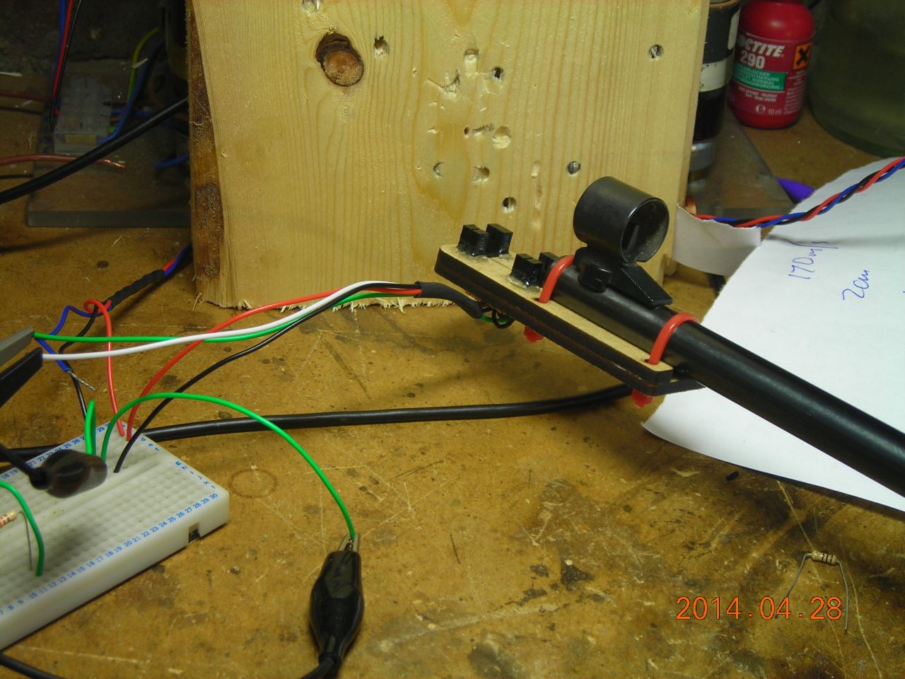
Obviously, the usual airgun safety rules apply. I wore a full-face mask, as well as glasses underneath, and made sure there was a hefty block of wood placed immediately behind where the pellet was striking. Although I didn't bother, some form of protection for the camera would be advisable (e.g. sheet of polycarbonate) since flying debris could damage the lens.
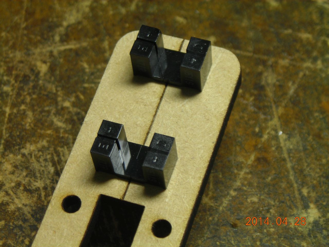
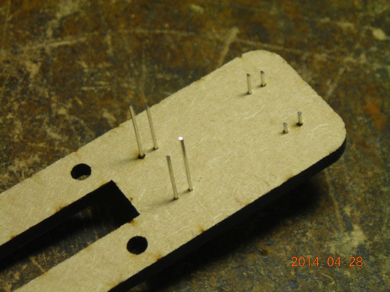
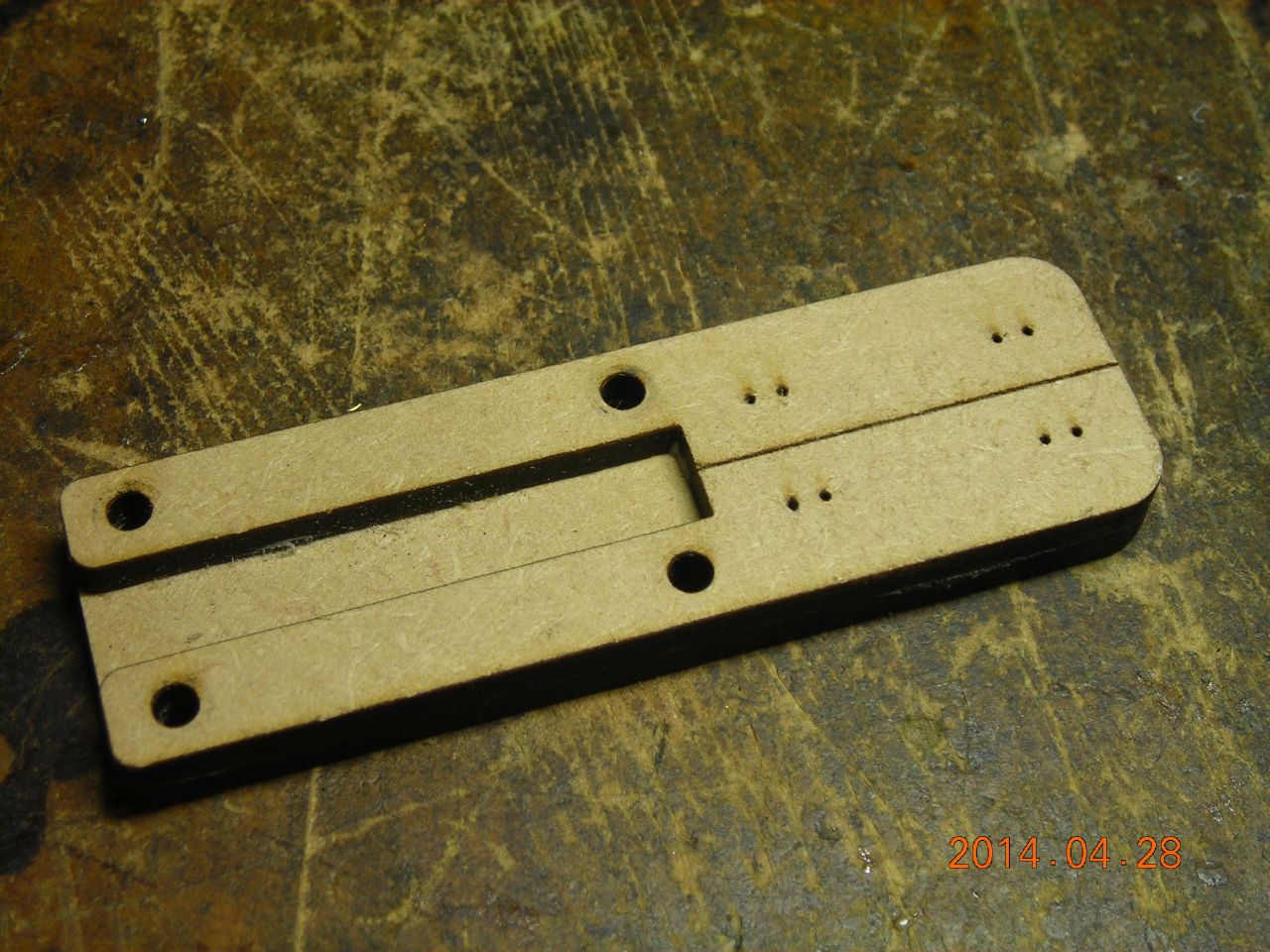
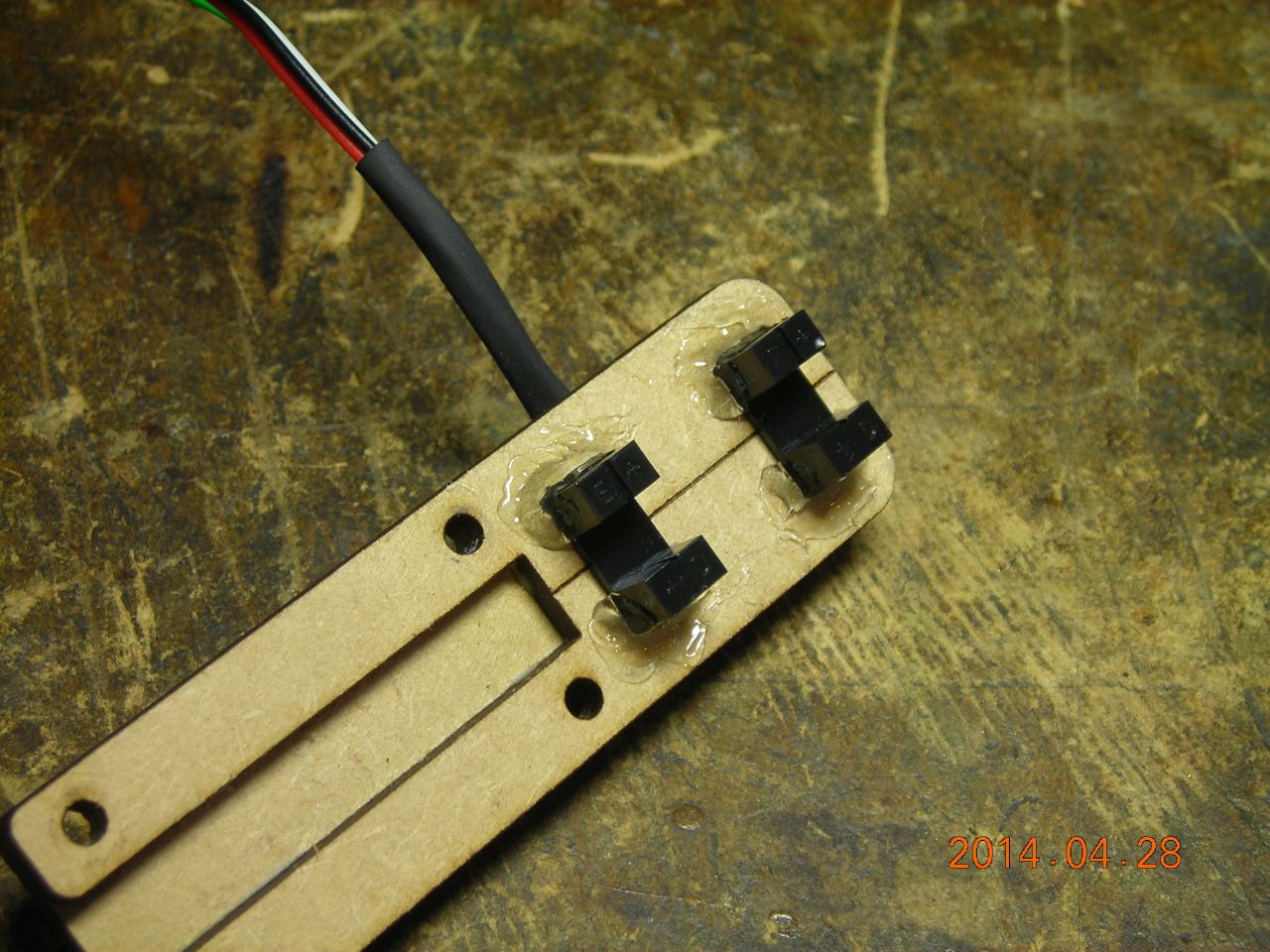
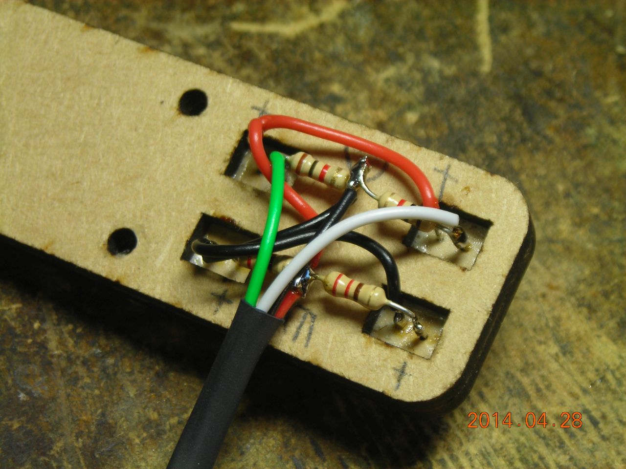
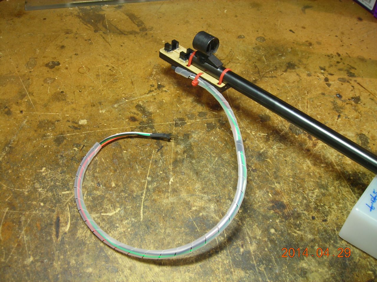
This little fitting was laser-cut from 3mm MDF and is attached to the end of the barrel with cable ties. The legs of the two slotted optical sensors (Kingbright KTIR0511S) are located in small holes in the wood, ensuring that they are aligned with the path of the pellet. The sensors are exactly 2cm apart.
Make sure the sensors used are reasonably fast - these have a response time of around 10µs, but I have seen similar slotted sensors with several hundred microseconds response, which isn't any good. Each LED is run from 5V with a 220Ω resistor, and the output transistor pulls up a 1kΩ load resistor to 5V (see later down the page for a circuit).
 |
 |
 |
 |
 |
 |
 |
 |
 |
 |
 |
 |
 |
 |
Here's a graph showing the outputs of both sensors as the pellet passes. The output is normally high, at around 2.5V, and goes low when the beam is blocked by the pellet. The time to travel between the two sensors is 113µs, corresponding to a velocity of 177m/s (the sensors are 2cm apart). This is very close to the manufacturer's quoted velocity of 170m/s. Additionally, the time for which the pellet blocks the sensor is 32µs, corresponding to 5.6mm, which is exactly the length of a pellet. Rather nice to see it all checks out.
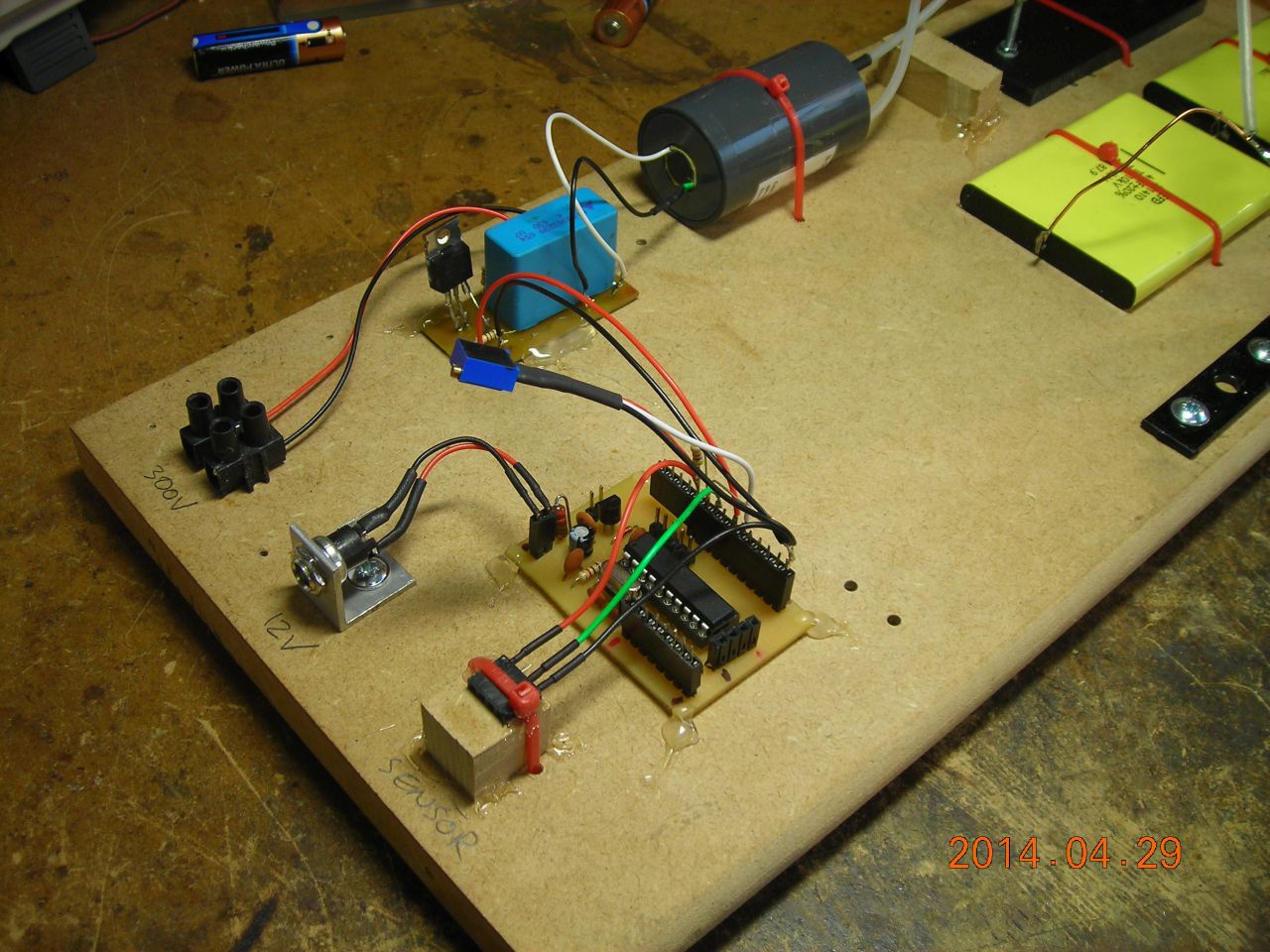
I used the pulse from the first sensor to trigger a PIC micro which delays a fixed amount of time, then produces a 50µs-long trigger pulse to a thyristor+trigger transformer assembly, which in turn fires a spark gap, producing illumination.
Here is a PDF of the circuit. Have a look through it and I'll describe the operation below. Also, here is the PIC code (MikroC).
Since the output voltage from the opto sensor isn't high enough to trigger a logic input directly, I'm using the PIC's internal comparator to check the opto sensor's output against a fixed voltage reference of about 1.6V. The voltage reference goes to RA0 and the opto sensor output to RA1. A 5kΩ potentiometer (connected to RC1) is also read by the PIC to adjust the delay time.
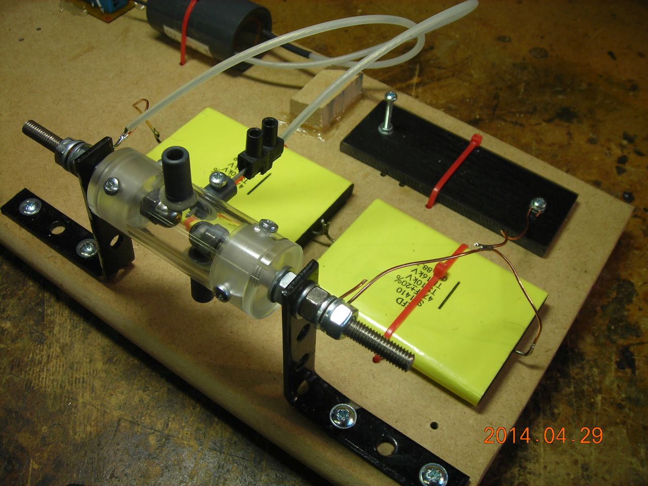
The trigger output is produced on RC0. This goes to a 16TTS08 thyristor via a 100Ω current-limiting resistor. A 1µF polypropylene capacitor is charged to 300V and is dumped through the primary of a trigger transformer when the thyristor is fired. The transformer itself is a custom job - it has 15 turns on the primary and 850 turns on the secondary. The core is half of a ferrite rod antenna. The secondary is vacuum-potted in epoxy. With a 300V input, it's capable of producing 20-30kV pulses, easily sufficient to trigger the gap.
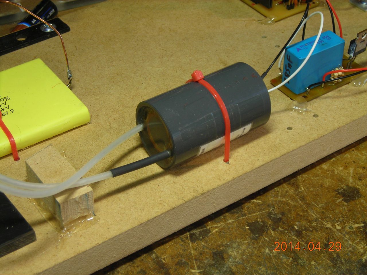
High-voltage stuff. A 15kV supply charges up two capacitors (connected in series to get suitable voltage rating) via a 20MΩ resistor. This is actually some diluted graphite coating painted on to a piece of acrylic - see here for details. The spark gap is two M6 stainless dome nuts inside an acrylic housing, with a sharp trigger electrode placed near one of them. An airflow is provided to keep the gas clean.
Quick software description. The PIC uses a comparator interrupt to detect the firing of the pellet. When the comparator interrupt fires, the PIC loads Timer 0 with a starting value and enables the timer overflow interrupt. When the overflow interrupt occurs, it then produces the 50µs trigger pulse. The timer starting value (0-255) is determined by the potentiometer setting - a higher starting value will result in a shorter delay time (less time to overflow). With the crystal and prescaler values used (18.432MHz crystal, 1:16 prescale), this gives a maximum delay of about 880µs, or around 15cm at 170m/s velocity.
 |
 |
 |
 |
 |
 |
 |
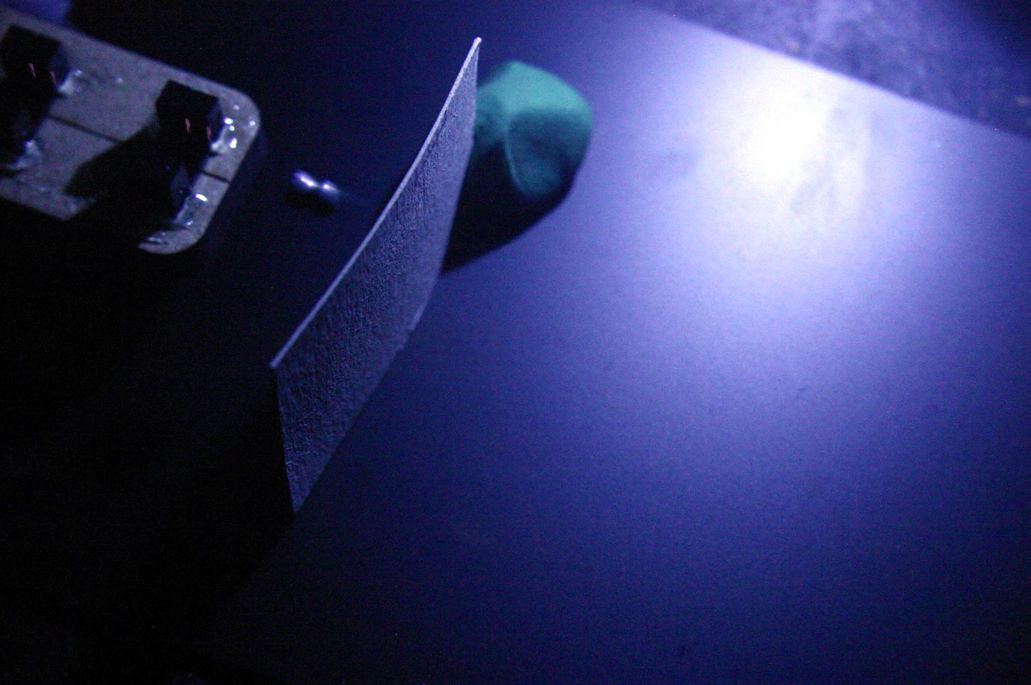
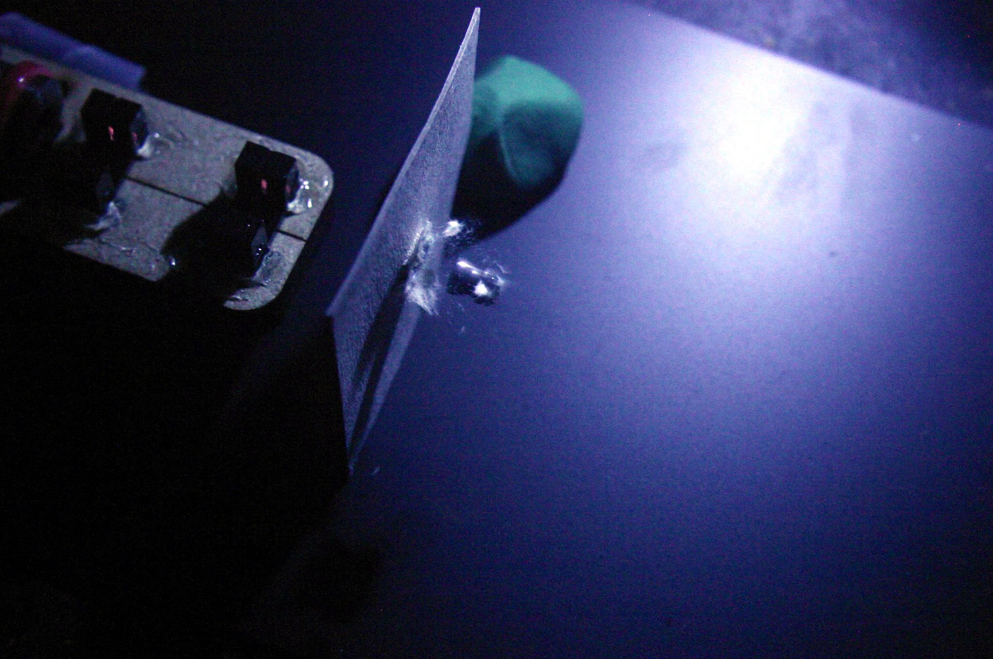
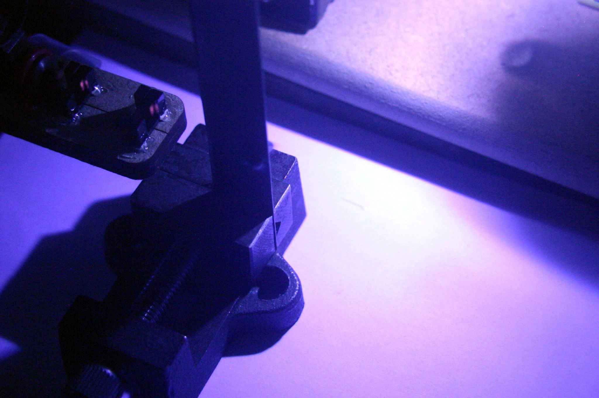
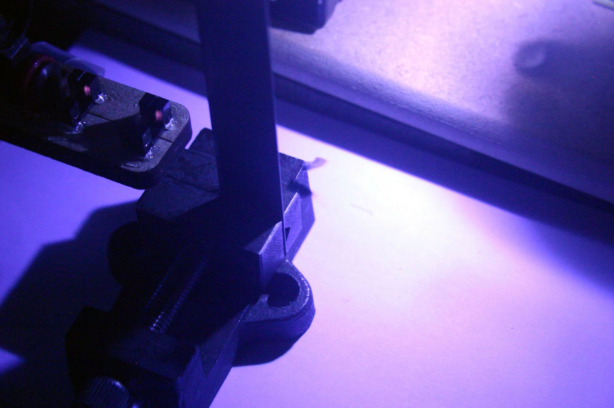
Here's a collection of all the shots I managed to take. The light isn't actually very bright, but it clearly froze the pellet nicely. The first three show the pellet in free flight, as I was adjusting the delay time from minimum to maximum. Next, the pellet passes through a piece of card (luckily I managed to get before and after shots). Finally, I fired the pellet at a craft knife blade to split it, and managed to get four progressive shots. The knife splits the pellet beautifully!
You can also just about see a dull orange glow from the emitters of the optical sensors - they're infrared, so the camera is sensitve to them.
Minimum delay (arrow indicates pellet) |
 Medium delay |
 Maximum delay - around 15cm, as expected |
 Card - before |
 Card - after |
 Knife 1 |
 Knife 2 |
 Knife 3 |
 Knife 4 |
I turned some of the images into animated GIFs - the knife splitting worked especially well.
| ▲ Optical |