| ▲ Optical |
This documents the assembly of a little UV laser diode module from various off-the-shelf parts. I originally constructed it mainly because a UV laser is a pretty neat thing to have, and the parts were very cheap. I've since discovered that the laser can expose photoresist directly, so there might be an actual use for it after all!
I initially looked around on EBay for anyone selling laser diodes. There's quite a few, but one that caught my attention was Odicforce (http://www.odicforce.com). They have a fantastic range of laser diodes, drivers, optics, mounts, and associated tools. Here is a list of the parts I bought from them:
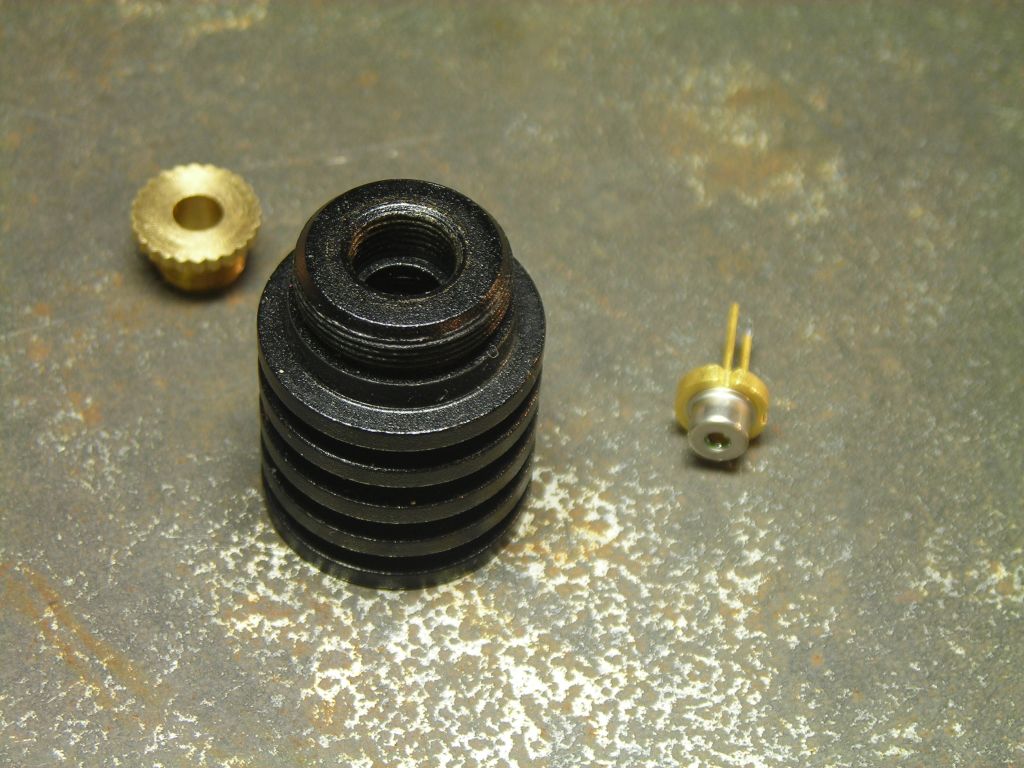
The laser diode housing comes with an acrylic lens, but I bought a glass lens as well to replace it since it's of higher quality.
Needless to say, this is a very powerful laser and can cause serious eye damage. The focused beam will burn surfaces. The usual safety warnings apply - don't look at the beam, in this case either directly or indirectly, and always wear suitable laser safety goggles when working with it. Although scattered light from the beam (e.g. shone on to a sheet of white paper) probably won't cause eye damage, I find it easily gives me a sore head very quickly, so do not even look at scattered light from it. In short, just wear goggles. For ever.
Laser diodes are extremely sensitive devices and can easily be damaged by static discharge. You must wear a grounded wrist strap when working with them, and preferably work on a grounded antistatic mat (lacking that, a grounded metal tray would suffice, which is what I used). There are various recipes for protecting laser diodes (parallel capacitors, mosfets, resistors), and there is a commercial component designed specifically for this purpose, the Lasorb (http://www.lasorb.com), but the laser diode should be pretty safe when it's connected to a dedicated driver module and enclosed in a housing, as it is here.
There is a small potentiometer on the driver board which can be used to set the current. I asked around for some advice on the best way to set this, and Rob Byron on the lasers@neurotica.com list suggested using a string of 6 1N4001 diodes and a 1Ω resistor in series as a dummy load. Measure the mV across the resistor and you get the mA current flowing. I hooked up the driver board to a 9V supply and adjusted the pot until I got about 95mA. This is a reasonable current for operating this particular laser diode. Rob also mentioned that the pot should not be adjusted with the laser diode connected because it may cause damage. Sometimes, when potentiometers are adjusted, the wiper can leave the track very briefly and this would cause a loss of regulation, with a possible increase in current through the diode.
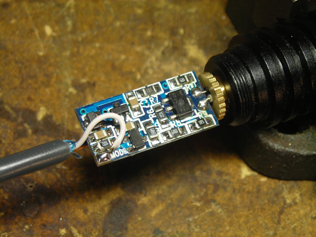
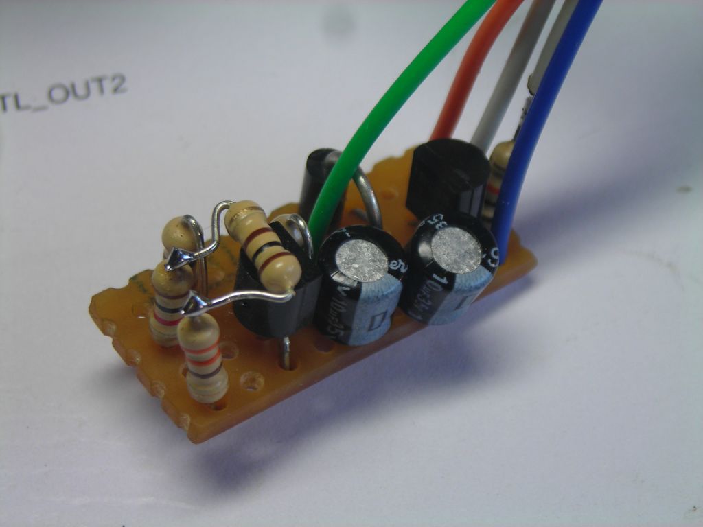
After the laser diode is attached to the driver board, it is possible to monitor the current through it by measuring the voltage across the relevant 1.5Ω resistor on the board - highlighted in yellow in the photo below. These are in series with the laser cathode. I measured about 140mV across the top-left one, corresponding to 95mA current.
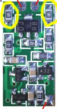
At 95mA, the laser diode drops 5.2V. The minimum input voltage for the driver board in order to get 95mA output current is 5.9V.
Although the case of the laser diode, and hence the housing, is negative, they are not at the same potential as the negative rail of the input power supply. Since the current-sense resistors mentioned above are between the diode cathode and ground, the cathode (and housing) will be at a few hundred mV relative to ground. Therefore, when mounting the housing, ensure that it's isolated from the power supply ground. If connection was made, I'd imagine that current control would be lost, damaging the diode.
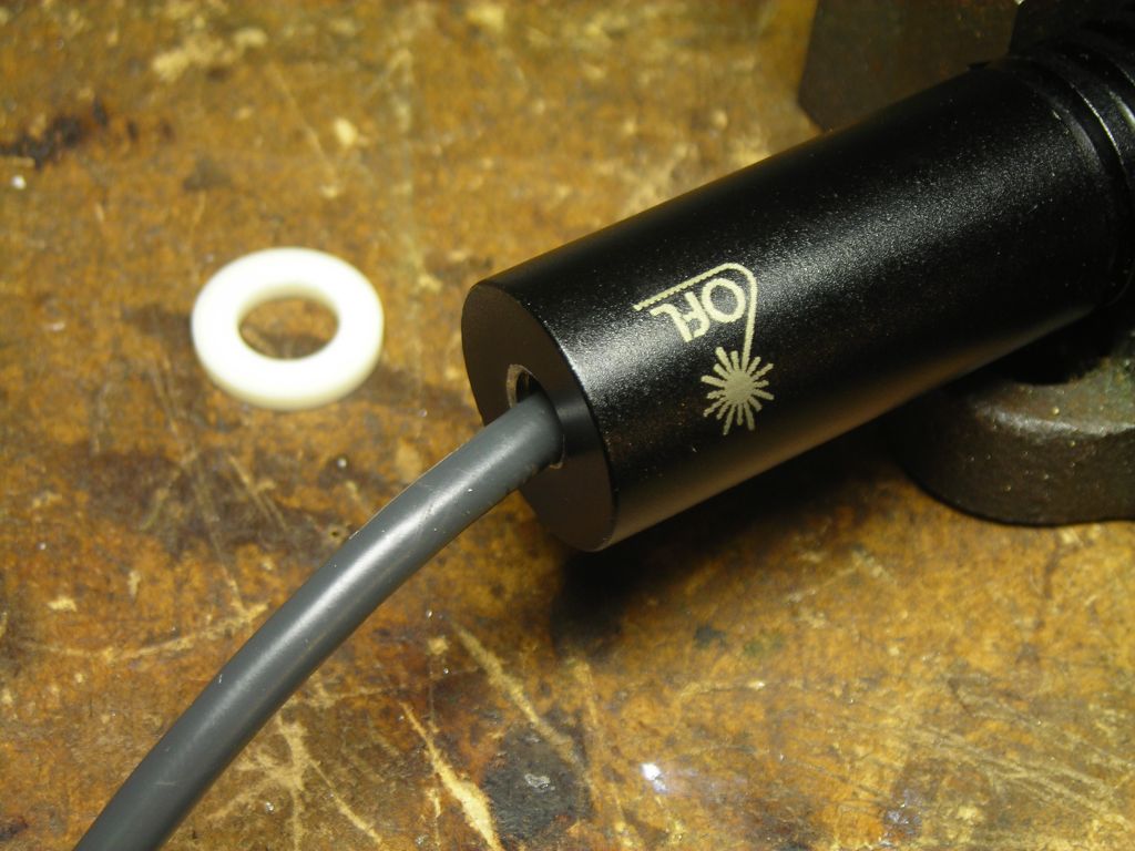
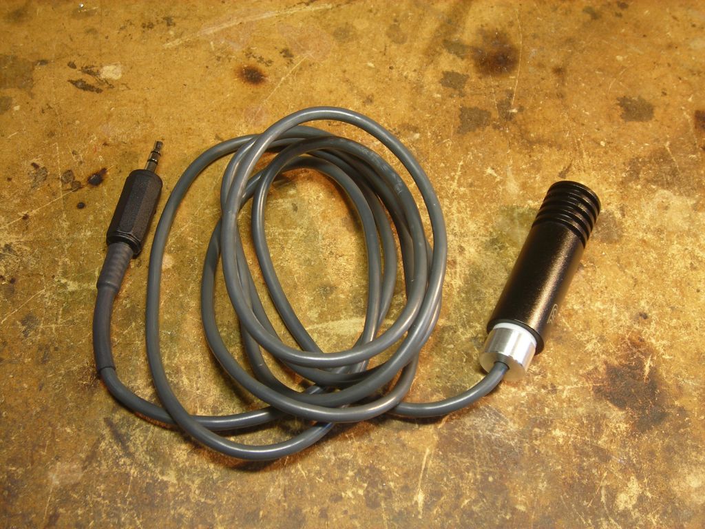
The laser diode and driver board are both mounted inside the housing. Three external connections are required to the driver board: 0V, + power, and TTL control. Since the backside of the driver board is very near the rear end of the housing, there's no space to knot the incoming cable, so I decided to make a small cable gland to hold the cable in place and prevent it pulling on the driver board. Photos below, but here are a couple of commercial mini cable glands which might be useful:
Hummel
Lapp Kabel
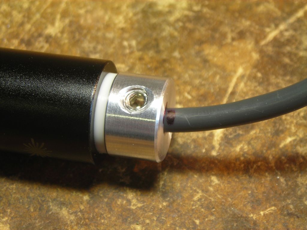
For cable, I used a piece from an old computer mouse since it was nice and flexible. A 3.5mm stereo plug at the other end connects to the power supply. I drilled out the rear of the laser diode housing and tapped it M6, then made a small aluminium gland which screws in and holds the cable with an M4 grubscrew (end sanded smooth so it doesn't cut through the cable).
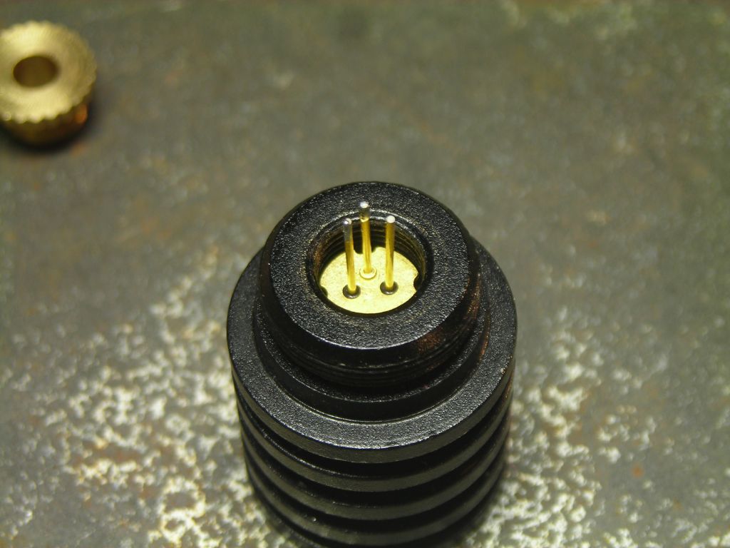
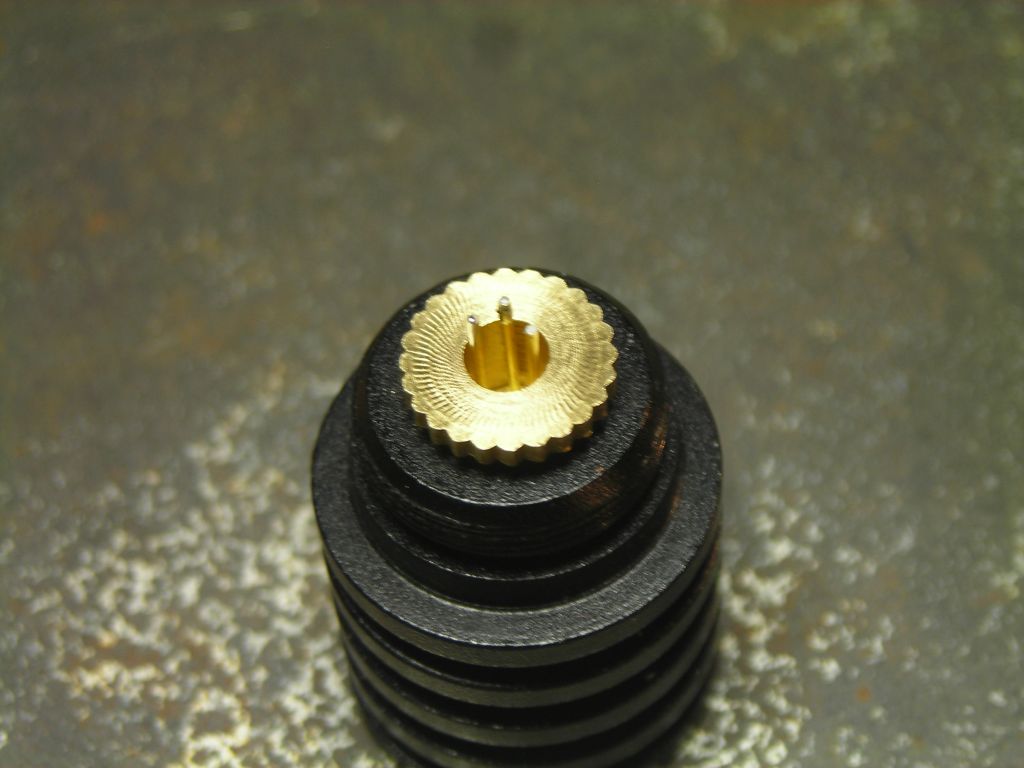
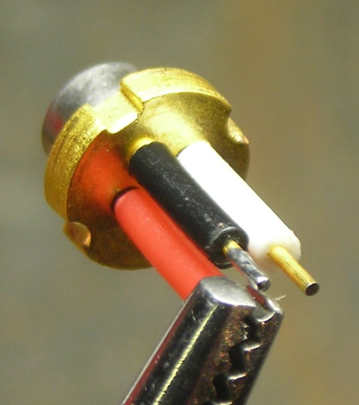
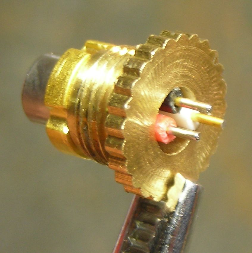
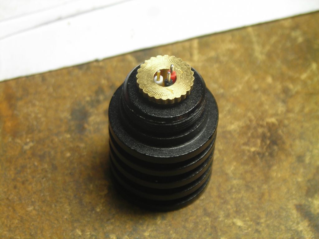
The leads of the laser diode itself were protected with some short pieces of insulation (from equipment wire), just in case they shorted against the retaining nut. A small amount of thermal grease was applied around the flange of the laser diode to enhance heat conduction.
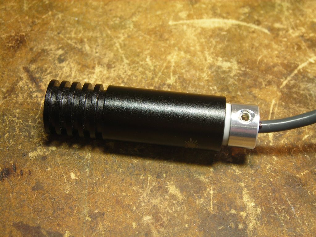
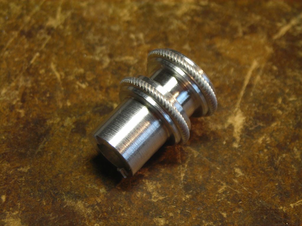
I also made a knob (with a rope knurl) to adjust the focussing lens with.
 |
 |
 |
 |
 |
 |
 |
 |
 |
 |
 |
 |
 |
 |
 |
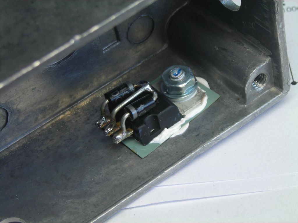
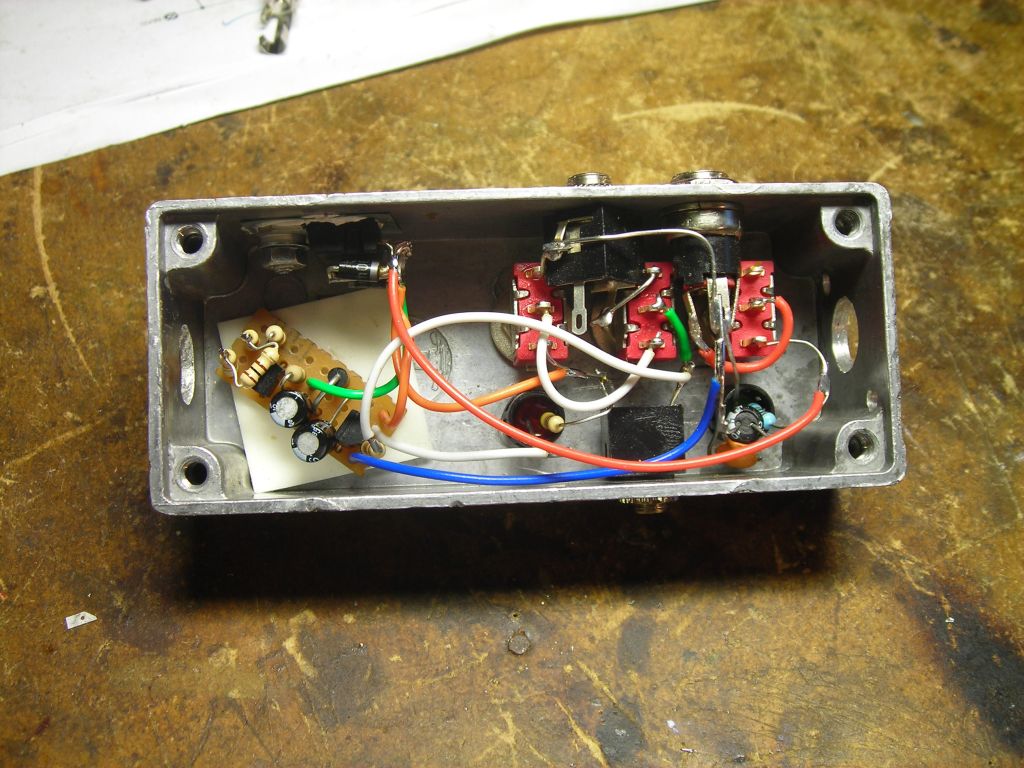
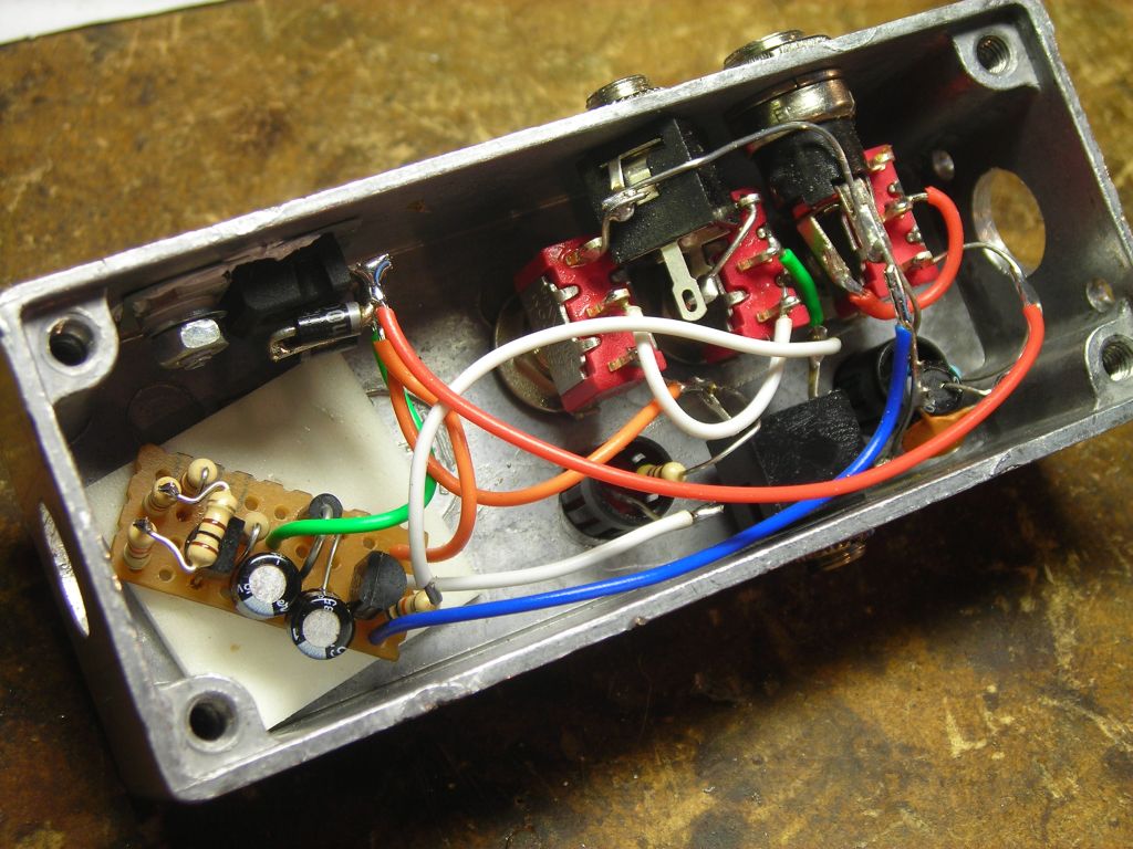
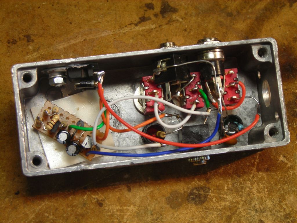
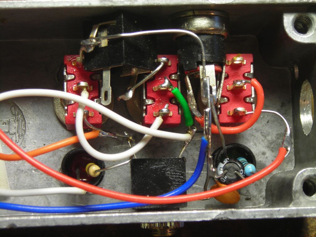
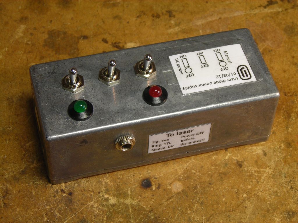
I built a small power supply circuit which takes 12V from a wall adaptor and converts it to a regulated 6.6V (approximately) output voltage for the laser. Since the minimum voltage required to run the laser driver module is 5.9V, 6.6V should be ample. You don't want too high a drive voltage, since the laser driver module has to drop the extra voltage, increasing power dissipation.
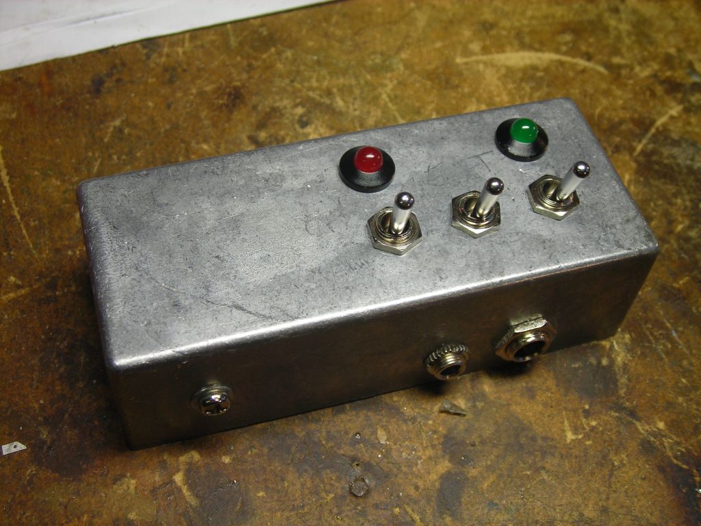
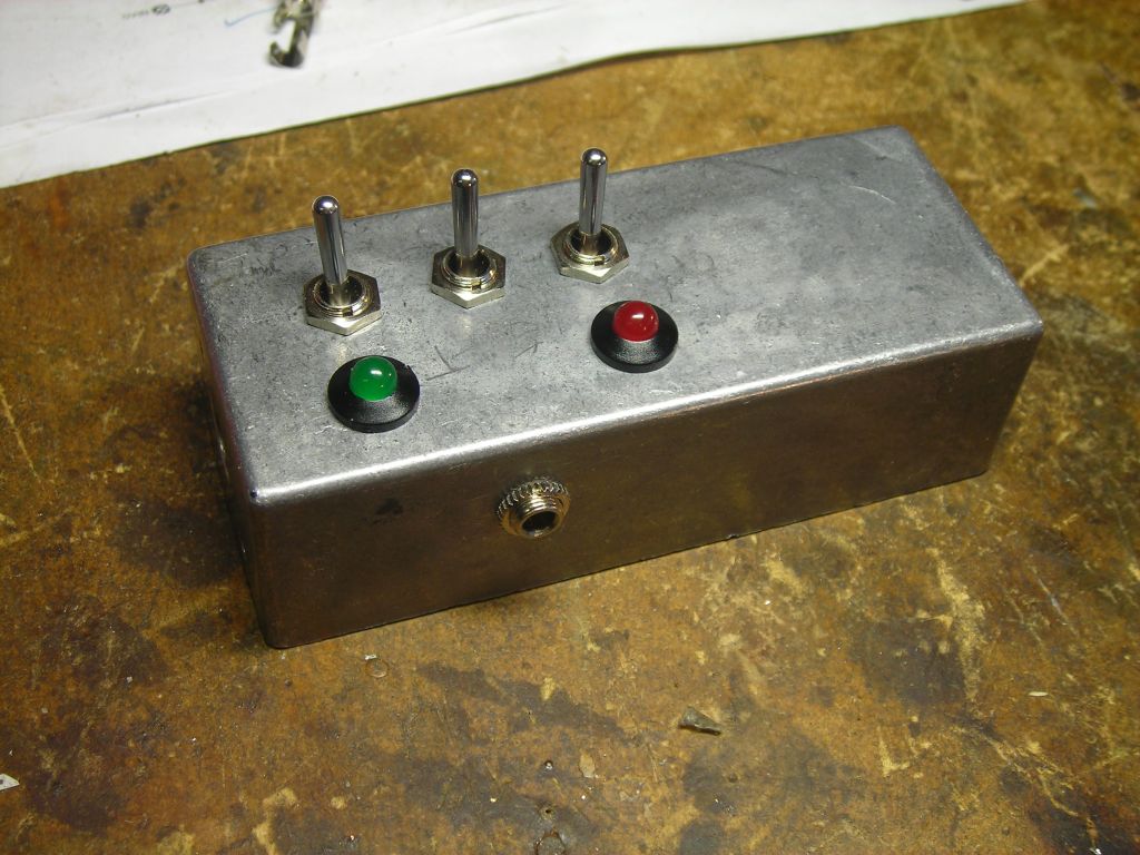
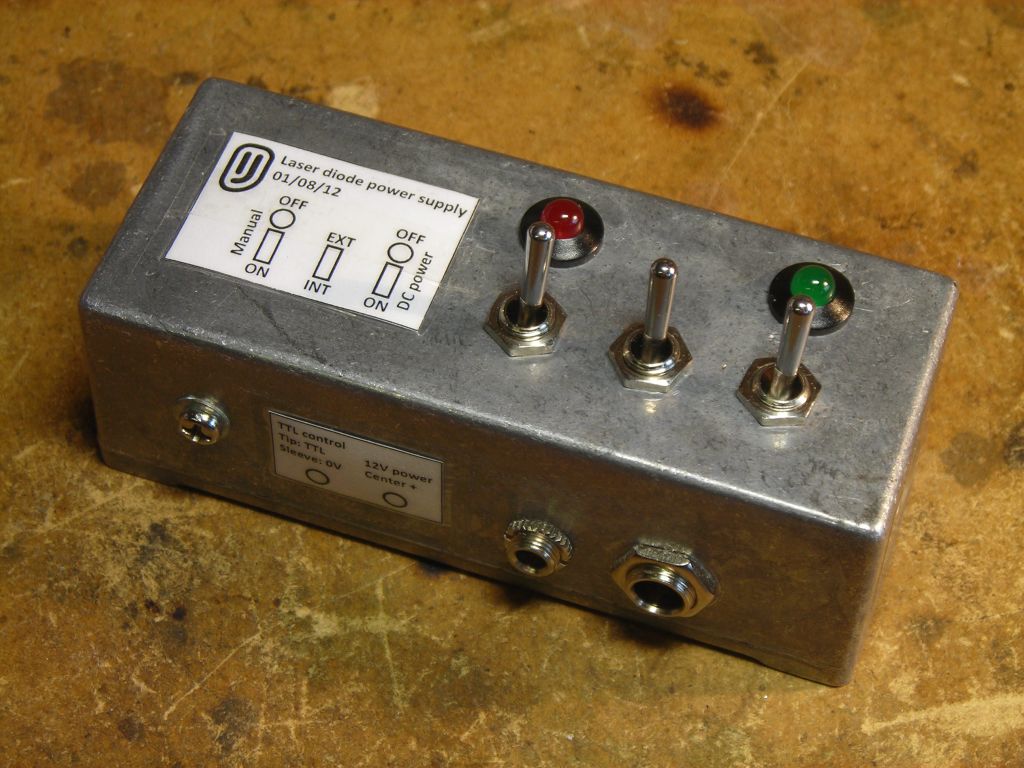
The power supply is built into a small diecast case which also has various switches to select internal/external TTL control, and another 3.5mm jack connector for external TTL control.
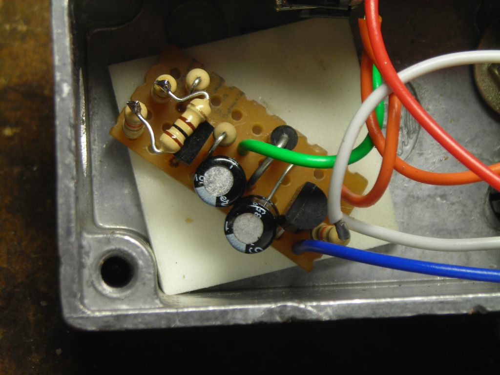
I used an LM317 linear regulator with a soft-start circuit in the power supply. Circuit is available here. The soft-start probably isn't essential, but I thought it better to be on the safe side. The rise time is about 2 seconds. Most of the small components are put on a small bit of stripboard. I had to play about a bit with the value of R2 to get 6.6V output. The "laser on" LED (LED2 in the circuit) only lights when power is supplied to the laser driver module and the TTL signal is high.
 |
 |
 |
 |
 |
 |
 |
 |
 |
 |
 |
 Rise time of output voltage |
Finally, here are some photos of it shining on different fluorescent objects. The beam can be collimated nicely and, if focused, will just about burn paper if held still. The five fluorescent dyes shown are from BASF's "Lumogen F" range and are all in PMMA (acrylic).
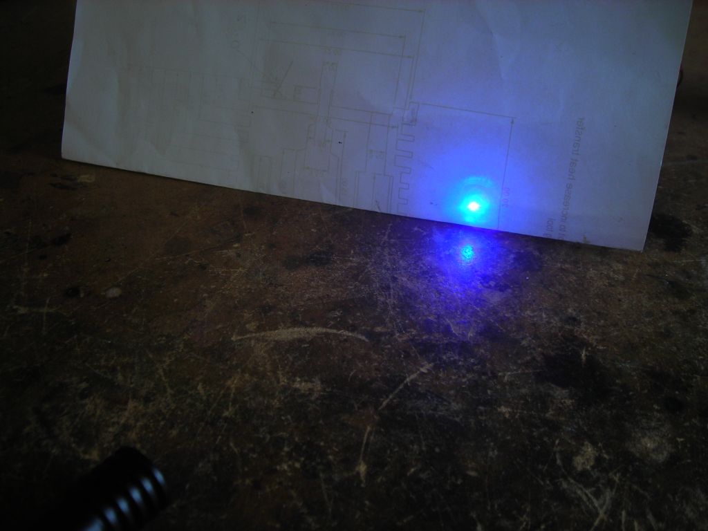 Paper |
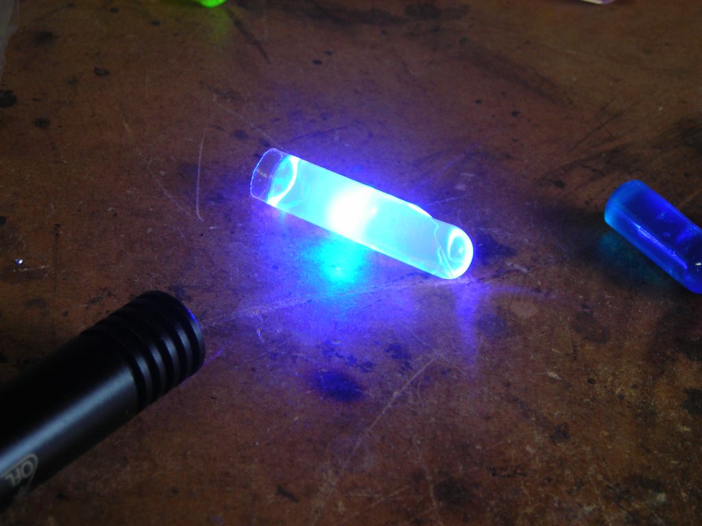 Violet 570 |
 Blue (can't remember number) |
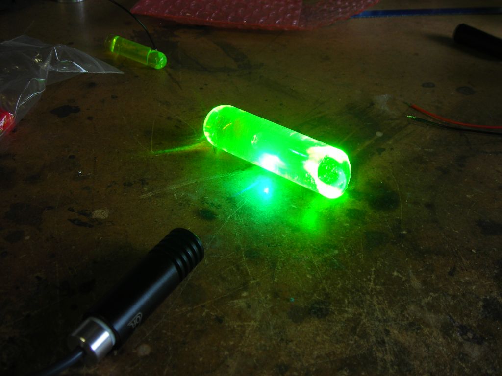 Green (can't remember number) or possibly Yellow 083 |
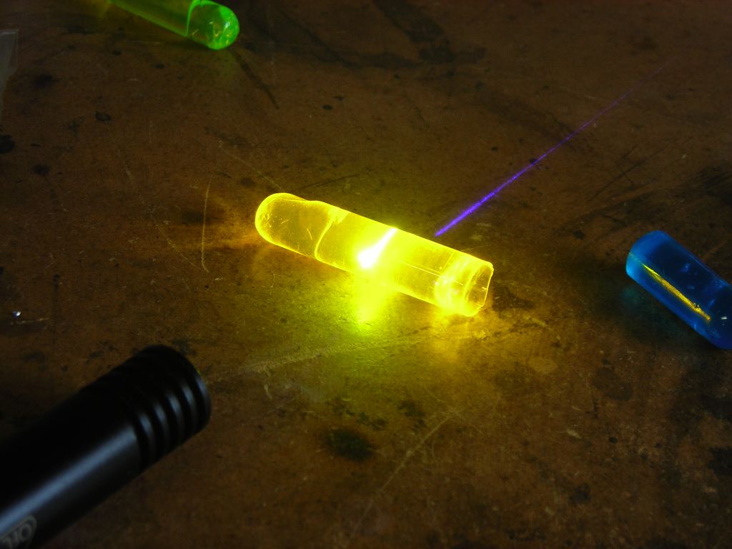 Orange 240 |
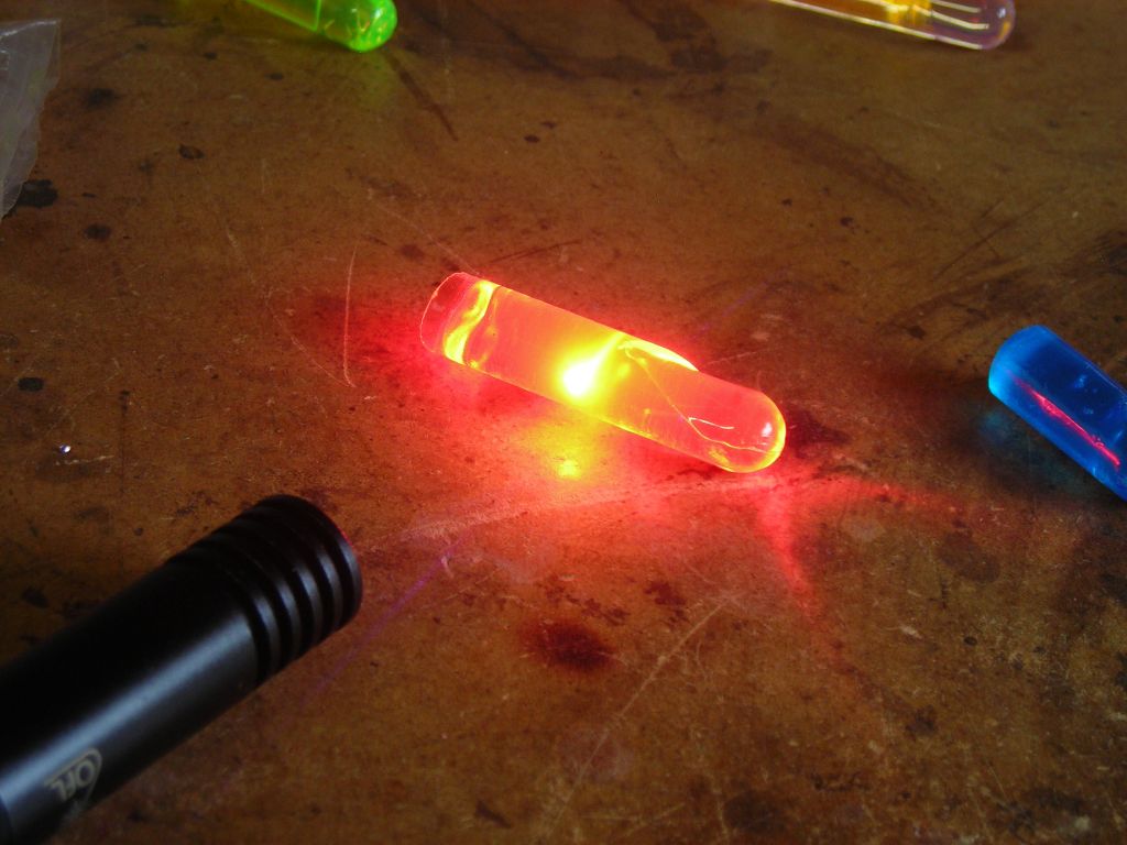 Red 305 |
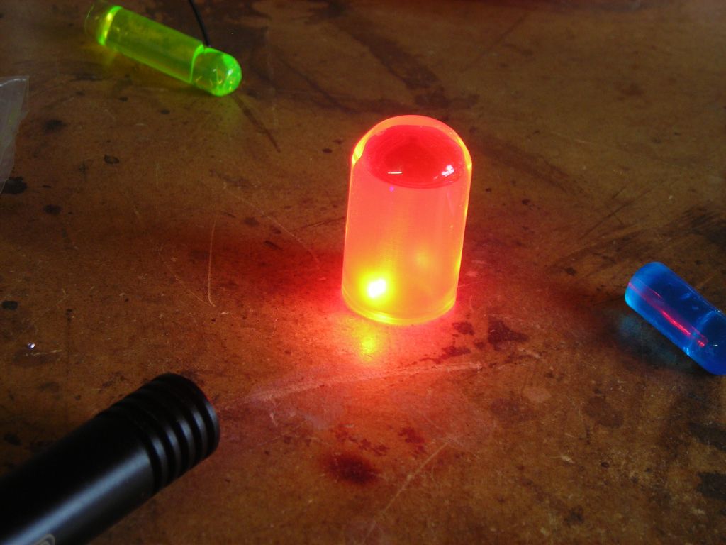 More Red 305 |
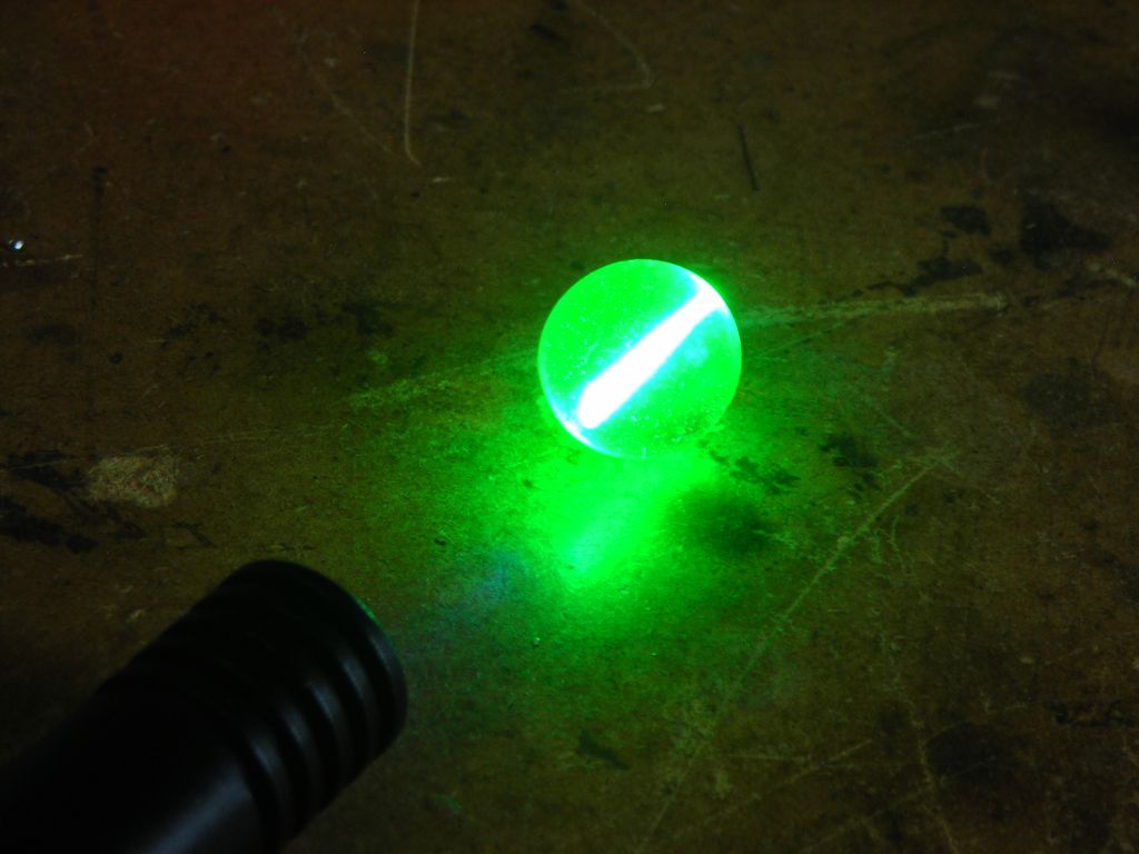 A uranium marble |
 Organo-metallic europium complex in PMMA, showing red europium fluorescence. |
 Some isopropanol that I use for cleaning PCBs - blue fluorescence. |
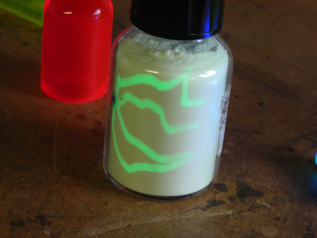 Trails left on a bottle of "Luminova" phosphorescent powder. |
Video showing the trails left on a bottle of "Luminova" phosphorescent pigment:
Here are some brilliant macro photos on the laser pointer forum of a bare 405nm diode during operation - http://laserpointerforums.com/f48/photos-405nm-laser-diode-photodiode-seen-off-under-microscope-74401.html.
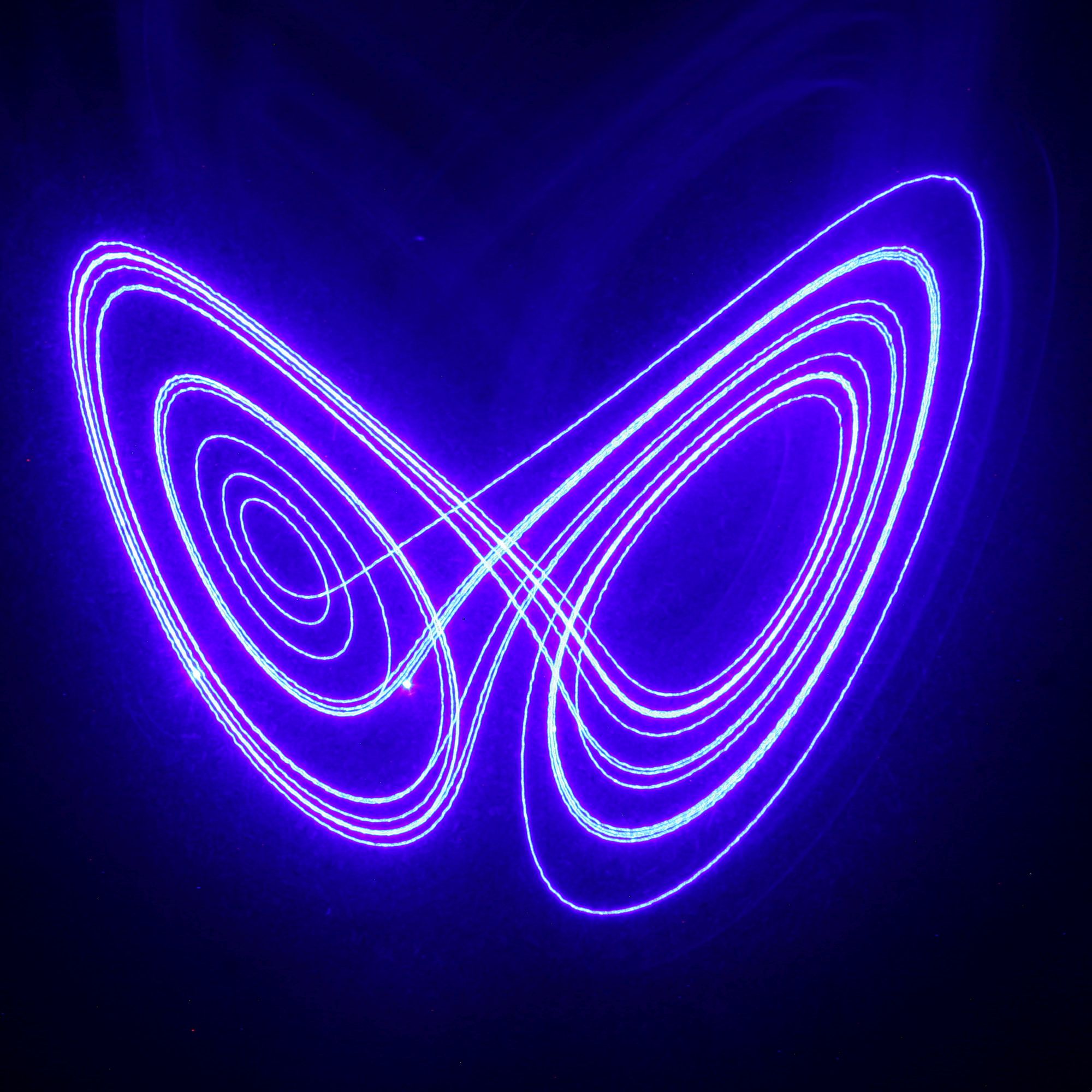
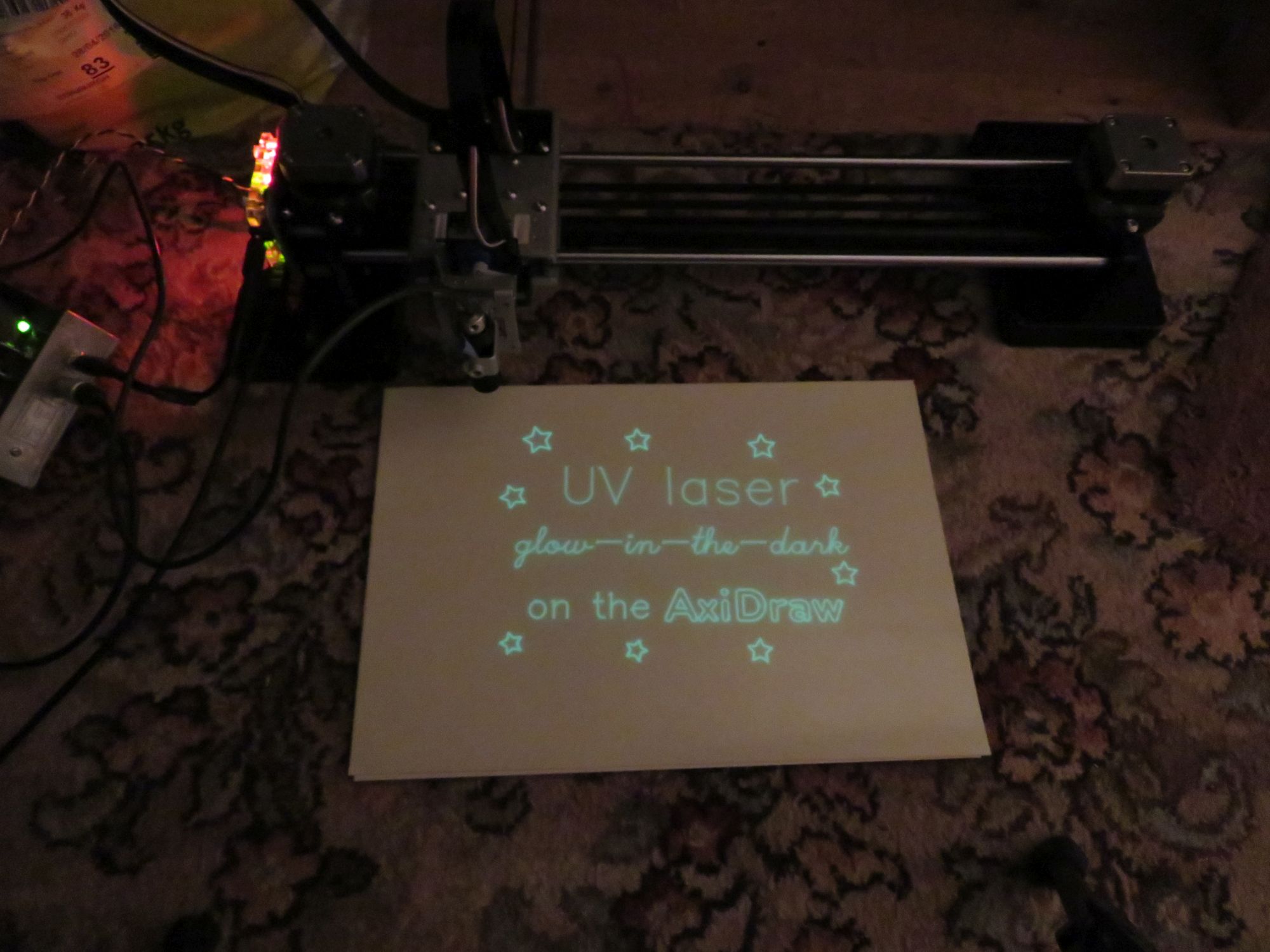
I mounted this laser module on my AxiDraw and tried both light painting and "drawing" on a sheet of glow in the dark vinyl. Both worked extremely well - check out the pages on using a laser on the AxiDraw and also on drawing the Lorenz attractor.
 |
 |
 |
 |
 |
 |
| ▲ Optical |